Sunday, 29 June 2014

Wideband RF Field Strength Meter


Field strength meter is extremely useful when working with RF devices. It can be used to quickly diagnose whether a transmitter circuit is working, and can be used to detect RF signals in the environment. The simplest field strength meter could be built with a tuned LC circuit and a germanium diode, just like the way of a building a crystal radio except replacing the ear piece with a high sensitivity current meter. While this approach fits the needs of most simple applications, it has a pretty narrow frequency range (~100 MHz) and requires tuning the LC circuit to the correct frequency before measurements can be made and the design can become complicated if wider frequency range tuning is desired.

Wideband RF Field Strength Meter

Another option is to use an RF detection chip. Most of such chips (from Linear Technologies, Maxim and Analog Devices) offer a very broad testing range and have much higher sensitivity and accuracy than a simple diode signal detector can offer. Here I will use Linear Technologies’ LT5534 RF detector chip as the field strength meter’s front end. Similar circuits can be build with other RF detection chips as well, depending on the types of the specific application.

LT5534 can detect RF signal from 50MHz all the way up to 3GHz, which covers most of the spectrum one typically uses. If your frequency spectrum is significantly different, you may check out the other RF detection chips the above mentioned companies offer.

The core detector circuit is almost identical to the reference design. The LM324 op-amp forms a differential amplifier with a gain of 2. The main purpose of this differential amplifier is to provide the ability to “zero” the meter reading or adjust the sensitivity of the detector. Since the differential op-amp’s output is proportional to the voltage difference between the output of LT5534 and the wiper voltage of the potential meter, we can adjust the potential meter to set the reference point (i.e. zero reading) for the environment. Also, by raising the wiper’s potential, it would take a higher output from the RF detector for the differential op-amp to register an input voltage and thus effectively lowered the sensitivity of the detector.
The output bandwidth of LT5534 is tens of MHz, since we do not care about the signal details in this particular application, the relatively low bandwidth LM324 has no impact on performance. The above circuit uses a 5V regulated power supply.

Saturday, 28 June 2014

5W1.5W 88-108Mhz FM Transmitter 14MHz (20m) AM Transmitter


This transmitter is designed to transmit sound (music, speech, ...) at frequencies 88-108MHz with a frequency modulation (FM). Its RF power is about 1.5 W. The first transistor is used as an RF oscillator. Varicap allows the oscillator frequency shifting and thus its frequency modulation and frequency tuning via potentiometer. Varicap may not be the BB105, it can be BB409, BB109G, KB109G or other type. The second transistor is the power output stage. The output signal goes through a filter to remove harmonics and then it enters antenna, eg dipole or Yagi antenna (it has better directivity). Power transistor is on the heatsink with min. 100 cm2 area. Coils are air, wire diameter of 0.6 mm wound on 5 mm.

     Warning! Operating this transmitter without permission is illegal.


1.5W 88-108Mhz FM power Transmitter schematic (note: "z" means number of turns)

40 Meter QRPp Transmitter


Steve Yates - AA5TB

40m QRPp Transmitter


I built this simple, crystal controlled 40 meter CW transmitter back in 1996. It sports full break-in operation and 250 mW of output power. The final output transistor is a mighty 2N2219A. The N6WG QSL card laying against the lid is just an example of one of the many contacts I have made with this transmitter. The station was located in California and my antenna was an inverted L (bent monopole) operated against a very poor ground system (a couple of ground rods). Considering the losses in my antenna system, I thought the contact was pretty good.

My design was based on one of the late Doug DeMaw's (W1FB) designs with many of my own modifications. The rig is built into an old file box I bought at a garage sale for $1.00.s

Inside View
Inside View

Schematic Diagram

Friday, 27 June 2014

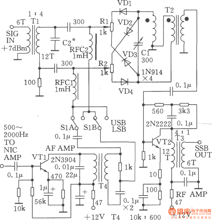
SSB signal generated by phase shift


SSB signal generated by phase shift
Home SSB transmitter is a challenge to the HAM and a test to its own power. But up to now little HAM can self-make SSB transmitter, the main reason is the core components of the transmitter SSB-crystal filter and the matching crystal (such as crystal filters are equipped with 9MHz the 8998.5kHz, 9001.5kHz crystal) is difficult to purchase in the country, in this case, the phase shift method can generate SSB signals, comparing with the commonly used filter, but it has the advantages of easy make, low-cost, particularly the output frequency of VFO (should have a very high degree of frequency stability) can be directly taken as the firing frequency, it does not have to go through one or more frequency, greatly simplifying the whole circuit , the circuit is shown as the chart.