Monday 14 February 2011

FM transmitter using UPC1651

Here is the circuit diagram of an FM transmitter using the IC UPC1651. UPC1651 is a wide band UHF Silicon MMIC amplifier. The IC has a broad frequency response to 1200MHz and power gain up to 19dB.The IC can be operated from 5V DC.The audio signals picked by the microphone are fed to the input pin (pin2) of the IC via capacitor C1. C1 acts as a noise filter. The modulated FM signal will be available at the output pin (pin4) of the IC. Inductor L1 and capacitor C3 forms the necessary LC circuit for creating the oscillations. Frequency of the transmitter can be varied by adjusting the capacitor C3.

Read more: http://www.circuitstoday.com/category/radio-circuits

1.5W 1-2 km Range FM Transmitter by 2N2219


1.5W 1-2 km Range FM Transmitter by 2N2219

This is a well designed basic FM transmitter that you can easily recive the signals transmitted from this transmitter in a 1-2km range with using a normal FM reciever. Another property of this circuit is that the bobin is placed on the printed circuit board. The input sound’s amplitude can be adjusted by using the P1 potentiometer.

Parts List:
R1 220K
R2 4.7K
R3,R4 10K
R5 100ohm
C1,C2 4.7uF electrolytic
C3,C4 1nF
C5 2-15pF
C6 3.3pF
Q1 BC547C
Q2 2N2219A
P1 25K
MIC ecm series

Source:http://www.circuit-projects.com/15-watt-1-2-km-range-fm-transmitter.html

FM surveillance BuG Transmitter using 2N2222

The Circuit shown can transmit voice to exceptionally good range. Tune trimmer to hear the signal to your near radio. Frequency range is 88-108 MHz. Max current consumption is 30mA. You can power the bug with a 9Volt Battery, or you can plug a power supply to feed in 9-12 Volts. That bug will pick even a low whisper or even the sound of a breath well far from the microphone. Great spy equipment.

Read more : http://www.next.gr/inside-circuits/FM-surveillance-BuG-Transmitter-l4105.html

CRYSTAL OSCILLATOR


This simple circuit will oscillate with a wide range of crystals. Connect several different types of crystal holders in parallel to improve versatility. The 3-to-40-uF capacitor adjusts crystal frequency over a small range for setting tostandard-frequency transmissions when the unit is used as a crystal calibrator.

Figure 1. Full Circuit of Crystal Oscillator

FM : Sound Transmitter

modulation (FM) is a form of modulation that represents information as variations in the instantaneous frequency of a carrier wave. (Contrast this with amplitude modulation, in which the amplitude of the carrier is varied while its frequency remains constant.) In analog applications, the carrier frequency is varied in direct proportion to changes in the amplitude of an input signal. Digital data can be represented by shifting the carrier frequency among a set of discrete values, a technique known as frequency-shift keying.

Figure 1. Schematics of FM : Sound Transmitter

HF 300KHz-30Mhz Linear Amplifier

This is a rather unusual QRP Power Amplifier design, with a wide frequency response; within three dB’s from 300KHz to 30MHz. Overall gain is in the region of 16dB and the final output power may be well over four watts. This PA will deliver 4 watts continuously (with a suitable heatsink), and may be loaded into a short-circuit or open circuit without causing damage. This makes it almost the ideal PA for outdoor/field use. Above is the full circuit diagram of the RFPA and the coil winding pattern. This PA may be used for for SSB.

Read more source:

http://w1.859.telia.com/~u85920178/tx/linear.htm

Mini ATU with Toroid

image

The toroid is wound with  28 turns tapped at 6,9,12,14,16,18,20,22,24 starting from LHS.

7 Mhz 5 watts QRP Transmitter

7MHZ QRP TX

80 Meter QRP Transmitter

80M QRP TX

80 Metre DSB Transmitter


This circuit is probably the simplest practical 'bare-bones' voice transmitter for the 3.5 MHz amateur band.

Unlike other simple transmitters, this one transmits DSB rather than AM. This makes it more compatible with SSB. Indeed, many SSB operators would not know that they're listening to a DSB signal if the signal is reasonably clean.

Another feature this rig boasts is frequency agility. As mentioned elsewhere on this web page, this is almost a must for any QRP transmitter. The use of a 3.58 MHz ceramic resonator allows coverage over the most active part of the 80 metre voice segment in Australia.

The VXO tunes about 3.550 to 3.620 MHz. A 10 – 160pF transistor radio tuning capacitor is used to adjust the frequency. A buffer amplifier isolates the VXO from the balanced modulator. The speech amplifier is a standard 741 op-amp circuit, as used in many transmitters by VK3XU. The balanced modulator is another common circuit. Any ferrite toroid, including TV balun cores, should suffice for the broadband inductor. The driver and PA draws heavily from the ZL2BMI 80m DSB transceiver designed in the NZART's 'Break In' in 1984. Output power is about 2 watts.

An optional feature included was an L-match antenna coupler. This provides impedance matching to a 40 metre-long end-fed wire antenna used for portable operation. It may be omitted if not required. If interference is a problem, extra sections can be added to the pi-network – details of the correct values to use appear in 'Solid State Design for the Radio Amateur'.

When construction is finished, connect an RF power meter/dummy load (see elsewhere on this website) and press the PTT. With an insulated screwdriver adjust the balance potentiometer. Tune for a null in output power – it should just move off the stop when the pot is near midpoint. Speaking into the microphone should result in the meter needle flicking up above 1 watt. The signal should sound clean in a nearby SSB receiver (disable the noise blanker and wind the RF gain control back first). The carrier signal should be well down on the sidebands. The final and driver transistors should not get too hot after these transmissions – if they do, improve heat sinking.

To reply to a station, press the PTT but do not talk. Adjust the tuning control so that the transmitter's carrier is zero beat. Then release the PTT. When your turn to transmit comes around you should be on frequency.

To convert to a transceiver, modify the switching so that the oscillator and buffer are on at all times. Then via a small coupling capacitor at the buffer's output tap off some local oscillator signal for the receiver's balanced mixer.


circuit of DSB transmitter

RF Signal generator

image

Power Oscillator


You can build a power oscillator with an NE592 and some additional parts. Depending on the crystal frequency, RF power generation in the range of 1 to 30 MHz is possible. The parallel resonant circuit C1/L1 must be tuned exactly to the crystal frequency. For final transistors one can use two 2N3906 or BS250 (see QRP push-pull amplifier). RF power output can be adjusted from 20 mW to 1.5 W by varying a common emitter resistor in the push-pull stage.

Do not use this circuit as a transmitter. When keying the NE592 power supply (pin 3) frequency variation (chirp) occurs. If you insist on transmitting with this circuit, then switch the final transistors directly. To do this put a 10 uH choke in series with the key and a 0.1 uF capacitor in parallel. Disadvantages of this circuit are the NE 592 quiescent current (18 mA), the continuously working oscillator and the hard keying.

Fig. 1: Power oscillator
{short description of image}</

INTERMEDIATE-FREQUENCY TRANSMITTER

2N3904,2N2222 circuit : INTERMEDIATE-FREQUENCY TRANSMITTER

The oscillator transmitter circuit is a variation of the Colpitts configuration. This particular circuit exhibits excellent frequency stability, good isolation between the frequency reference and the output, and isolated low output impedance. If you have the correct crystal on hand, that's fine. If not, a ceramic resonator will also work with the components shown. The tuned circuit T1 is an IF "can," salvaged from an old AM and FM receiver; be sure that it has a primary tap. The primary of the 455-KHz, IF can will measure 3 to 5Ω, and the 10.7-MHz IF can will measure less than 1Ω; these measurements will help you to identify the correct inductor. The components in parentheses should be used for the 455-kHz transmitter.

HF Push Pull Broad Band Amplifier Circuit

By N.S. Harisankar VU3NSH.

This HF Push Pull Broad Band RF Amp will give 50W output and it is useful to RM96 output stage. All components are soldered on the copper foil side (Track side). For fixing the FETs, use Mica insulation and Nylon bush. Connect the drain connection via eylets at the Top (FET’s Drain pin is not directly used in this PCB). Keep P1 & P2 at -ve (zero) position. Connect a 250 ma meter at the supply line (LK .- Link). Set the P1 for 20ma and P2 for 20ma. The total drain current of 40ma.

If you are using this circuit as a separate unit then connect Carrier Operated Relay (COR) and connect VT +ve supply to VCC line with proper dropping circuit to 7805 input. After setting the drain current 40 ma, then connect 0 to 5 Ammeter or VU meter with proper shunt for TX power indication at link line. PCB is available with the author (VU3NSH). All components in this PCB are on the Track side, so use adequate insulation on component / fix all components 2 to 3 mm above the Track side to avoid shorting.

Circuit Diagram of HF Push Pull PA
PCB layout of HF Push Pull PA

Fig.1 Circuit Diagram of HF Push Pull PA
Fig.2 PCB layout of HF Push Pull PA


HF Power Amplifiers

VU2VKC's RF. PA STAGE
VU2VJY's RF. PA STAGE

Fig.3 VU2VKC's RF. PA STAGE
Fig.4 VU2VJY's RF. PA STAGE

Variable RF attenuator with PIN diode


Variable RF attenuators are often used to control the level of a radio frequency signal using a control voltage in RF design. These variable RF attenuators can even be used in programmable RF attenuators. Here the known voltage generated by a computer for example can be applied to the circuit and in this way create a programmable RF attenuator.

Often when designing or using variable or programmable RF attenuators, it is necessary to ensure that the RF attenuator retains a constant impedance over its operating range to ensure the correct operation of the interfacing circuitry. This RF attenuator circuit shown below provides a good match to 50 ohms over its operating range.

RF attenuator circuit description


The PIN diode variable attenuator is used to give attenuation over a range of about 20 dB and can be used in 50 ohm systems. The inductor L1 along with the capacitors C4 and C5 are included to prevent signal leakage from D1 to D2 that would impair the performance of the circuit.

The maximum attenuation is achieved when Vin is at a minimum. At this point current from the supply V+ turns the diodes D1 and D2 on effectively shorting the signal to ground. D3 is then reverse biased. When Vin is increased the diodes D1 and D2 become reverse biased, and D3 becomes forward biased, allowing the signal to pass through the circuit.


Typical values for the variable RF attenuator circuit might be: +V : 5 volts; Vin : 0 - 6 volts; D1 to D3 HP5082-3080 PIN diodes; R1 2k2; R2 : 1k; R3 2k7; L1 is self resonant above the operating frequency, but sufficient to give isolation between the diodes D1 and D2.
These values are only a starting point for an experimental design, and are only provided as such. The circuit may not be suitable in all instances.

Choice of PIN diode

Although in theory any diode could be used in variable RF attenuators, PIN diodes have a number of advantages. In the first place they are more linear than ordinary PN junction diodes. This means that in their action as a radio frequency switch they do not create as many spurious products and additionally as an attenuator they have a more useful curve. Secondly when reverse biased and switched off, the depletion layer is wider than with an ordinary diode and this provides for greater isolation when switching or providing higher levels of attenuation.

Simple FM transmitter with a Single Transistor


Mini FM transmitters take place as one of the standard circuit types in an amateur electronics fan's beginning steps. When done right, they provide very clear wireless sound transmission through an ordinary FM radio over a remarkable distance. I've seen lots of designs through the years, some of them were so simple, some of them were powerful, some of them were hard to build etc.

Here is the last step of this evolution, the most stable, smallest, problemless, and energy saving champion of this race. Circuit given below will serve as a durable and versatile FM transmitter till you break or crush it's PCB. Frequency is determined by a parallel L-C resonance circuit and shifts very slow as battery drains out.

Technical datas:

Supply voltage : 1.1 - 3 Volts
Power consumption : 1.8 mA at 1.5 Volts
Range : 30 meters max. at 1.5 Volts

Main advantage of this circuit is that power supply is a 1.5Volts cell (any size) which makes it possible to fix PCB and the battery into very tight places. Transmitter even runs with standard NiCd rechargeable cells, for example a 750mAh AA size battery runs it about 500 hours (while it drags 1.4mA at 1.24V) which equals to 20 days. This way circuit especially valuable in amateur spy operations :)

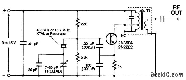
Transistor is not a critical part of the circuit, but selecting a high frequency / low noise one contributes the sound quality and range of the transmitter. PN2222A, 2N2222A, BFxxx series, BC109B, C, and even well known BC238 runs perfect. Key to a well functioning, low consumption circuit is to use a high hFE / low Ceb (internal junction capacity) transistor.

Not all of the condenser microphones are the same in electrical characteristics, so after operating the circuit, use a 10K variable resistance instead of the 5.6K, which supplies current to the internal amplifier of microphone, and adjust it to an optimum point where sound is best in amplitude and quality. Then note the value of the variable resistor and replace it with a fixed one.

The critical part is the inductance L which should be handmade. Get an enameled copper wire of 0.5mm (AWG24) and round two loose loops having a diameter of 4-5mm. Wire size may vary as well. Rest of the work is much dependent on your level of knowledge and experience on inductances: Have an FM radio near the circuit and set frequency where is no reception. Apply power to the circuit and put a iron rod into the inductance loops to chance it's value. When you find the right point, adjust inductance's looseness and, if required, number of turns. Once it's OK, you may use trimmer capacitor to make further frequency adjustments. You may get help of a experienced person on this point. Do not forget to fix inductance by pouring some glue onto it against external forces. If the reception on the radio lost in a few meters range, than it's probably caused by a wrong coil adjustment and you are in fact listening to a harmonic of the transmitter instead of the center frequency. Place radio far away from the circuit and re-adjust. An oscilloscope would make it easier, if you know how to use it in this case. Unfortunately I don't have any :(

Every part should fit on the following PCB easily. Pay attention to the transistor's leads which should be connected right. Also try to connect trimmer capacitor's moving part to the + side, which may help unwanted frequency shift while adjusting. PCB drawing should be printed at 300DPI, here is a TIFF file already set.


The one below is a past PCB work of mine, which was prepared to fit into a pocket flashlight. Since it was so crowded, use the new computerized PCB artwork instead, yet very small. Take a look at PCB design page to get information on my work style.
Source: http://tacashi.tripod.com

AM/FM/SW active antenna


These materials are provided as-is, with no support. They are not being maintained. At present they are being kept available because we're aware people still refer to them - but we reserve the right to remove this archive, without notice, at any time.


This circuit shows an active antenna that can be used for AM, FM, and shortwave (SW). On the shortwave band this active antenna is comparable to a 20 to 30 foot wire antenna. This circuit is designed to be used on receivers that use untuned wire antennas, such as inexpensive units and car radios. L1 can be selected for the application. A 470uH coil works on lower frequencies ( AM ). For shortwave, try a 20uH coil. The unit can be powered by a 9 volt battery. If a power supply is used, bypass the power supply with a .04uF capacitor to prevent noise pickup. The antenna used on this circuit is a standard 18" telescoping type. Output is taken from jack J1 and run to the input on the receiver.

Active antenna 1 to 20dB, 1-30 MHz range.


by

Rodney A. Kreuter Tony van Roon

"When fate or nasty neighbors prevent you from stringing a long-wire receiving antenna, you'll find that this pocket-size antenna will give the same, or even better, reception. This "Active Antenna" is cheap to build" and has a range of 1 to 30Mhz at between 14 and 20dB gain."

For conventional all-frequency short-wave reception, the general rule is "the longer the antennal the stronger the received signal." Unfortunately, between nasty neighbors, restrictive housing rules, and real-estate plots not much larger than a postage stamp, short-wave antennae often turn out to be a few feet of wire thrown out of the window--rather than the 130 feet of long-wire antennal we would really like to string between two 50-foot towers.Fortunately, there is a convenient alternative to the long-wire antenna, and that's an active antenna; which basically consists of a very short antenna and a high-gain amplifier. My own unit has been in operation successfully for almost a decade. It works satisfactory.

The concept of a active antenna is fairly simple. Since the antenna is physically small, it doesn't intercept as much energy as a larger antenna, so we simply use a built-in RF amplifier to make up for the apparent signal "loss." Also, the amplifier provides impedance matching, because most receivers are designed to work with a 50-ohm antenna.

Active antennas can be built for any frequency range, but they are more commonly used from VLF (10KHz or so) to about 30MHz. The reason for that is because full-size antennas for those frequencies are often much too long for the available space. At higher frequencies, it is quite easy to design a relatively small high-gain antenna.The active antenna shown below (Fig. 1), provides 14-20dB gain at the popular short-wave and radio-amateur frequencies of 1-30MHz. As you would expect, the lower the frequency the greater the gain. A gain of 20dB is typical from 1-18 MHz, decreasing to 14dB at 30MHz.
Circuit Design:
Because antennas that are much shorter than 1/4 wavelength present a very small and highly reactive impedance that is dependent on the received frequency, no attempt was made to match the antenna's impedance--it would prove too difficult and frustrating to match impedances over a decade of frequency coverage. Instead, the input stage (Q1) is an JFET source-follower, whose high-impedance input successfully bridges the antenna's characteristics at any frequency. Although many different types of JFET's may be used--such as the MPF102, NTE451, or the 2N4416--bear in mind that the overall high-frequency response is set by the characteristics of the JFET amplifier.

Transistor Q2 is used as an emitter-follower to provide a high-impedance load for Q1, but more importantly, it provides a low drive impedance for common-emitter amplifier Q3, which provides all of the amplifier's voltage gain. The most important parameter of Q3 is fT, the high-frequency cut-off, which should be in the range of 200-400 MHz. A 2N3904, or a 2N2222 works well for Q3.
The most important of Q3's circuit parameters is the voltage drop across R8: The greater the drop, the greater the gain. However, the passband decreases as Q3's gain is increase.

Transistor Q4 transform Q3's relatively moderate output impedance into a low impedance, thereby providing sufficient drive for a receiver's 50-ohm antenna-input impedance.

Active Antenna Schematic Diagram (C)

Active Antenna for AM/FM/SW

Active Antenna for AM/FM/SW

This simple little circuit can be used for AM, FM, and Shortwave(SW). On the shortwave band this active antenna is comparable to a 20 to 30 foot wire antenna. It is further more designed to be used on receivers that use untuned wire antennas, such as inexpensive units and car radios.
MPF102/NTE451 - N-Chan JFET

Parts List:
R1 = 1M
C1 = 470pF
C2 = 470pF
L1 = 20uH to 470uH (see text)
Q1 = MPF102, 2N4416, or NTE451


A KIT is available and may contain any value uH for L1, between 20uH and 470uH, to get you started. Change this value to suit your needs.
Parts only, no pcb: [Parts KIT]


L1 can be selected for the application. A 470uH coil works on lower frequencies and lie in AM, for shortwave try a 20uH coil. The KIT is supplied with a value whatever is available up to 500uH. The color code for L1 is generally yellow-violet-brown for a 470uH type but still this can vary by the type of inductor.


This unit can be powered by a 9 volt alkaline battery. If a power supply is used, bypass the power supply with a 0.04uF capacitor to prevent noise pickup. The antenna used on this circuit is a standard 18-inch telescoping type, but a thick piece of copper, bus-bar, or piano wire will also work fine.


The heart of this circuit is Q1, a JFET-N-Channel, UHF/VHF amplifier in a TO-92 case. Although many different types of FET's may be used--such as the MPF102, or the 2N4416--bear in mind that the overall high-frequency response is set by the characteristics of the FET amplifier. The direct replacement for the MPF102 is the NTE451. Second runner up is the 2N4416.


Output is taken from jack J1 and run to the antenna-input of your receiver.
Although this little circuit can easily be mounted on a piece of vero-board, I have supplied the printed circuit board and layout diagram if you wish to make your own.


Active Antenna PCB Active Antenna Lay-out

Folded dipole

The folded dipole has several interesting features.

  • A two wire folded dipole can increase the characteristic feed impedance of a dipole and offer a good match to 300 Ohm balanced feed line.

  • A three wire folded dipole can increase the characteristic impedance of a dipole and offer a good match to 450 Ohm or 600 Ohm balanced feed line.

  • Offers a better match over a wider band, which can be important on the lower frequency bands.

  • When fed with a balanced feed line, and an antenna tuner, it can be run on multiple bands. This assumes that it is 1/2 wavelength long at your lowest operating frequency.

The drawing below shows the essential elements of a folded dipole. It consists of two parallel elements having a constant spacing s. These elements can be anything from simple wires to copper or aluminum tubing. The bottom element is split in the center and serves as the feedpoint. The upper element has a diameter d2 and the bottom element has a diameter d1. The ends of the elements are connected to form a continuous loop from the feedpoint.

The relationship of those three dimensions, (s, d1, and d2) creates a impedance transformation at the feedpoint that is described by the equation on the right. The Ratio, when multiplied by the standard dipole feed impedance, describes the folded dipole feed impedance.

Design Data

In the text areas to the right, enter your initial design information. Enter your expected frequency of operation, the antenna velocity factor, and the nominal feed impedance of a simple dipole.

The velocity factor is to adjust for the fact that the propogation of energy in a wire is a little slower than in free space. The value is based on the length to diameter ratio and defaults here to 0.951. Larger diameters may require you to adjust this value slightly higher.

The folded dipole multiplies the normal feed impedance of a simple dipole. For a 1/2 wave dipole, in free space, this is approximately 72 Ohms. You may not be dealing with a dipole in free space, but 72 Ohms is close enough to start with. You can adjust it to other impedances in the appropriate text box below.

Then enter the dimensions for your folded dipole antenna. If you make the diameter of both radiator elements, d1 and d2, equal the transformation ratio will be 4. This should transform the 72 Ohm simple dipole feed impedance to about 288 Ohms. You should note that, when the two diameters are equal, the distance s does not change the transformation ratio. Use the text areas below to enter diameters of each element and the distance between them. You can enter the the data in any dimension you like. You can even mix and match. Output data is presented in both US/Imperial and Metric dimensions.