Tuesday 15 February 2011

Simple and Powerful FM transmitter

This simple FM Transmitter is very powerful (mean its not simple one..! but its easy to make..).  You can transmit FM signals up to 5km radius circle area using this Transmitter. I recommend to use 12V battery for supplying power. If you wish to use 12V AC-DC adapter you may want to make a very smooth DC out put using stabilizer, unless it will generate low frequency hum when listening to FM radio out put. For making L1 coil use 18SWG copper wire (about 1mm diameter) and make 7 turns(see figure 2). Use 75Ω TV cable's middle wire for antenna, It should be 2meters long(see figure 3).

figure1


Making the coil(use 18SWG copper wire or around to it)>>

figure2


Antenna(Use this cable for best results, otherwise you can use any type of copper wire(at least 2meters long))>>

figure 3


Transistor pin identification>>

Low Cost Powerful AM Transmitter (13Km)

This is a simple AM Transmitter Circuit, but Its very powerful one. It can transmit SW range signals within 13Km circular area. Use external antenna for best results. I recommend to use 12V battery as the power supply. If you hope to using 12V AC-DC adapter you may want to keep very smooth DC out put using stabilizer, unless it will generate low frequency hum when listening to radio out put.  Better to read following instructions before assembling the circuit.

>

> L1 Coil

Use 22SWG copper wire and make 10 turns, Insert a ferrite rod in to the coil. see figure 1.

>> L2 Coil
Use 22SWG Copper wire and make 10 turns. Don't use a ferrite rod. Coil diameter is 0.6 cm ( 1/4' ).
>> X-tal (Crystal)
Use 4.4333MHz crystal.

Push-pull Linear Amplifier with NE592 Driver


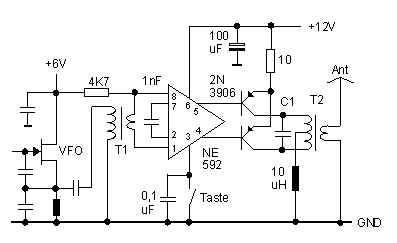
Transformer T1 matches the relatively low impedance present at the VFO FET gate to the balanced inputs of the NE592. With a unipolar power supply, it is necessary to bias both inputs to roughly one-half of Vcc. Below, we have shown both inputs tied to +6 VDC, conveniently available from the VFO. If 6 volts were not available, we would employ a scheme identical to the "IF amplifier" shown earlier, with Vcc split in half with 2 4,7K-ohm resistors in a divider configuration, applied to both inputs. Normally, stage gain is determined by the value of a resistor between pins 2 & 7. Bench tests reveal better output symmetry, however, if we replace this resistor with a 1 nF capacitor.

Approximately 8 volts of RF drive is available at pins 4&5 if we don't load it too heavily. This is sufficient to drive a pair of 2N3906 PNP transistors in push-pull to roughly 1,5 watts output with excellent efficiency. With bias provided by the NE592, the output transistors are operated in their linear region. Push-pull operation provides inherent suppression of even-order harmonics (2f, 4f, etc.), thereby simplifying our output network design (not shown). T2 is a T44-2 toroid with 5 bifilar primary turns and a single 5 turn secondary. C1 is around 270 pF (for 10 MHz), and should be adjusted to resonate the primary of T2 to signal frequency.

Fig 1: Schematic of the push-pull final (Pin designations are for the 8 pin DIP package)
{short description of image}

A tuned transform tank does not like to see a severely reactive load. An antenna tuner or some other means of cancelling reactance and transforming impedance must be employed if the load departs significantly from 50+j0 ohms. Broadband transformers, on the other hand, are inherently less sensitive to mismatch because of their low Q, but must be backed up with an effective harmonic suppression filter to achieve acceptable spectral purity. A single pi-network should do it. A low Q parallel-resonant circuit (low L, high C) was also tried, with acceptable results.

VFO

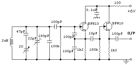
The VFO  was a Colpitts oscillator using two BFW10's.

  • Use RFC in place of 1K2 Resistor if Oscillator doesn’t start
  • RFC can be constructed by winding 150 turns 36 swg enameled wire on a 100K, ½ W Resistor.

simple solidstate CW transmitter

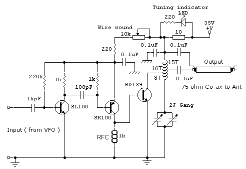
QRP TX was a simple solidstate CW transmitter using SL100, SK100 and BD139 giving about 5Watts on 40 Mtr band. This circuit was popular in South India and was known as ' VWN' circuit.

  • A RFC similar to the one used in the VFO circuit is used in SK100 collector to ground end.
  • BD139 Tank coil is 4.4 uH and is wound with 24 swg enameled copper wire on a piece of polythene pipe of 1.7 cms OD & lenght 3 cms. Tap at 13th , 15th  and 16th turns. 13th tap can be used for 50 Ohms coax/ inverted 'V' Ant or 15th tap can be used for 75Ohm coax/ Dipole Ant.
  • Mount BD139 on a heatsink.
  • Keep input current (BD139) at less than 200mA.

60W Linear amplifier


The 60 Watt linear amplifier is simple all solid state circuit using power mosfet IRF840. The IRF series of power transistors are available in various voltage and power ratings. A single IRF840 can handle maximum power output of 125 watts. Since these transistors are used in inverters and smps they are easily available for around Rs: 20/-.

The IRF linear amplifier can be connected to the out put of popular VWN-QRP to get an output of 60 Watts. The circuit draws 700 ma at 60 Volt Vcc. Good heat sink is a must for the power transistor.

Alignment of the circuit is very easy. Connect a dummy load to the out put of the circuit. You can use some small bulb like 24V 6Watts as the dummy load. I have even used 230V 60Watts bulb as dummy load with my IRF840 power amplifier working at 120Volts. Adjust the 10K preset to get around 100 ma Drain current. I used gate voltage of 0.8V with my linear amplifier. A heigh gate voltage can make the power transistor get distroyed by self oscillation. So gate voltage must be below 2V and fixing at 1V will be safe.

Bifalar transformaer T1 is wound with 8 turns 26SWG on 1.4 x 1 balun core.
The coil on the drain of IRF is 3 turns 20 SWG wound on 4 number of T13.9 torroids (two torroids are stacked to form a balun core). The RFC at the Vcc line is 20 Turns 20 SWG wound on T20 torroid.

10 watt RF amplifier for 18MHz by 2SC1969


10 watt RF amplifier for 18MHz by 2SC1969

This project and your efforts will provide you with a 0.55…3 watt input to easily 10 watt output. The two linear amplifiers are ment for use with QRP SSB/CW/FM/AM transmitters on the amateur bands 15 and 17 meters can be powered from a 12 volt DC supply. The design is a good balance between output power, physical size. The completed amplifier will reward the builder with a clean, more powerful output signal for a QRP rig when radio conditions become marginal.

Linear Amplifier used in 7MHz SSB Ham Radio Transceiver


The linear amplifier consists of 2N2222, SL100 and BD139. Heat sink should be provided for SL100 and BD139. All coils are wound on balun core. Some of the DC voltages measured are given below. These voltages are measured with out any input using digital multimeter.

Linear Amplifier used in 7MHz SSB Ham Radio Transceiver using 2N2222A, SL100B and BD139.

QRP ATTENUATOR AND LINEAR AMPLIFIER


After building my homebrew DSB transceiver and making some good contacts it was sometimes very frustrating with only 1 watt of power. I was recommended this excellent circuit by Andy Small (M0DRN) to use as an afterburner. As you can see from the diagram it is very easy to build and the amp circuit itself is between the two dotted lines. If your QRP transmitter is more than 1watt then you will have to build the attenuator circuit to reduce the power to the required input level. The amplifier requires 0.5watt to 1 watt of power to operate so it has made a perfect matching QRP amp for my DSB rig. I decided to fit a bypass switch so I could use the unit as a separate attenuator and check the power on other homebrew rigs before putting any signal through the amp.

Following the amp on the right side of the dotted line is a low pass filter which I would highly recommend as this will greatly reduce any harmonics making for a much cleaner transmission. The filter components above are for the 40M band but if you want to operate the amp on another band you only need to change the filter component values.

CONSTRUCTION

I have built my amplifier on a piece of single sided copper PCB and cut out small insulated islands to solder the components on. T1 was made by cutting two pieces of enamelled copper wire about 300mm long. I placed the wires side by side and clamped one end in a vice. The wires were then twisted together keeping the tension on all the time making around 3 turns per cm. The two wires are then treated as one and I made ten turns through the T 50-43 core. The enamel was scraped off the edge of the wires and tined ready to be soldered. To avoid confusion each of the two wires was checked with a multimeter, but another way is to mark the wire ends with coloured ink. The polarity of these wires are very important and must be correct.

The setting up procedure is simple. Once you have attenuated your signal to the correct drive level switch the power on and with a multimeter set the initial gate voltage to 3volts. Do this procedure while the amp is idling and not in transmit. This will give around 5watts output ideal for QRP operating. Adjusting the voltage to 3.5 volts will increase the power to 8watts. I have had 10watts output from the amp but only operate it at 5watts. The circuit uses the popular IRF510 transistor and will need a heatsink with a smear of petroleum jelly or heat compound to dissipate the heat. The drain leg of the transistor is electrically connected to the metal tag inside, so the drain leg was lifted clear of the PCB and a solder tag was fitted to the fixing nut for the drain connection to the T1 bifilar transformer. The drain connection must be insulated from ground so I cut out an island on the PCB to mound the transistor and heatsink which also helps with the heat dissipation. The PCB was then bolted onto four stand offs inside an aluminium enclosure and when all the sockets, dials and switches had been fitted it looked a nice finished project ready for testing.

http://www.gameangler.eu/delboy/m0dad/construcion/qrp_attenuator_and_linear_amplif.htm

TOBACCO TIN TRANSMITTER


I would like to show you my novelty transmitter project which I have enclosed into a tobacco tin. It requires very few parts, they are very easy to obtain, most of them came from my junk box with the exception of the crystal (7.030 MHz) which is an international QRP calling frequency. Any crystal will do as long as the operating frequency is within the amateur band, preferably in the CW section.

CIRCUIT

This is a one transistor crystal controlled transmitter, it uses the 2N2222 transistor in a basic oscillator arrangement, and has a simple output filter section for any unwanted harmonics. If the output filter was not used  the transmitted frequency would not only be 7.030 MHz but also 14.060 and 28.120 MHz etc. These unwanted frequencies are called harmonics. The output power is only 250 milliwatts (quarter of a watt) but high harmonic output is illegal even at this low power.  

CONSTRUCTION

I have used the ugly style construction, this is where you start with an off cut of copper clad board material, and build the circuit on the copper side up. The copper surface makes a low impedance ground and a anchor point for components. The grounded or copper surfaced components make a good solid support for the rest of the circuit to be built on. It is up to you as the builder which style you use, but the ugly construction is a lot cheaper than buying expensive vero board or making a printed circuit board. As you can see from the diagram there are very few parts, and it is straight forward to build. RFC1 is 6 turns of 32 s.w.g. enamelled copper wire wound on a tiny ferrite bead, any thin wire and ferrite bead should work. The toroid in the output filter section is 14 turns of 26 s.w.g enamelled copper wire wound around a T50-2 core.

OPERATING

When you have finished just press your morse key, no tune up procedure is necessary. You will also need an HF receiver, or shortwave radio with a BFO to operate with, I use a Realistic DX-394 receiver with an indoor wire and the transmitter next to the receiver with any of my outdoor antennas, but you could operate both from one antenna with a changeover switch. Although the transmitter only has 250 miliwatts this circuit when connected to a good outdoor antenna such as a dipole in favorable conditions has worked DX over 7000 miles. You will notice I have left a space on the right hand side of the box, this is to put an optional PP3 9 volt battery inside if I am going portable.

OTHER BANDS

The transmitter can also be  built to work on 80, 30 and 20 meters with the crystal of your choice, and the following changes=

80 meters =T50-2 toroid 21 turns capacitors 1, 2 and 3 =750 pfd

30 meters = T50-2 toroid 13 turns capacitors 1,2 and 3 =330pfd

20 meters =T50-2 toroid 12 turns capacitors  1, 2 and 3=270pfd

Please note It is illegal to operate this transmitter without an hf license.

http://www.gameangler.eu/delboy/m0dad/construcion/tobacco_tin_transmitter.htm

End-Fed Random Length Antenna

image

Below is another end-fed antenna made from a random length of wire connected to the back of the tuner. The wire then exits the shack and goes to a high support where it then runs horizontally to another high support. The tuners groundside must be connected to a good RF ground, since a poor ground causes high losses. This antenna is commonly called a "long wire." Since the end of the antenna comes in the shack, you will be exposed to high levels of RF. In addition, this type of installation may cause RF to be picked up in the microphone, noted by distortion. The feed-point of the long wire being connected directly at the output of the tuner can have an impedance of a few ohms to a thousand ohms depending on the antennas length. If the wire is cut to a multiple of a half wave at the lowest frequency, the system will be efficient since it is fed at a voltage point and very little current flows into the ground. This antenna is really a variation of an inverted-L fed directly without a feed-line from the tuner.

Designing RF Probes


An RF probe is used to directly measure the level of RF voltage present at a particular point and is one of the most useful test instrument in the hands of the home brewer. It is normally used with a digital multi meter to indicate the voltage level as dc voltage which is equivalent to the RMS value of the RF voltage being measured.

However, the level of RF voltage being measured provides useful information only when the probe has been designed for use with a specific multi meter. The design of the RF probe is a function of the DC input resistance of the meter we intend to use with it. If a new meter with a different input resistance is used with the probe the reading will be inaccurate.

Look at the figure below which shows the construction of the RF probe. The rectified DC voltage at the cathode of the diode is at about the peak level of the RF voltage at the tip. The value of the resistor R1 is so chosen that when this resistor is connected in parallel with the input resistance of the digital multi meter, the peak value is about 1.414 times the RMS voltage. R1 has to drop this excess voltage so the meter indication is accurate. If we know the input resistance of the meter, we can calculate the value of R1 as follows. Usually, digital multi meters have an input resistance of 11 meg ohms. In this example we shall take the input resistance of the meter as 10 meg ohms which will make calculation easier to understand.

10,000,000 X 1.414 = 14,140,000

R1 = 14,140,000 - 10,000,000 = 4,140,000 Ohms = 4.14 Meg Ohms

4.7 meg ohms is the value chosen in all circuits since digital multimeters have input resistance of 11 meg ohms.

Circuit By RAMASWAMI VU2PRI.

Building RF Probes.

RF Dummy Load


According to the radio regulations in most countries, any licenced radio amateur must have a non-radiating load to connect to his transmitter's RF output. The use of such a load is mandatory for off-air adjustment of the transmitter.

The load described here is capable of handling up to 10 watts of RF power for a couple of minutes, and is designed for the widely used 50 ohms impedance. It consists of ten parallel connected 560 ohms 1 watt resistors, R1 through R10, a voltage divider, R11-R12, and a rectifier D1-C1. Apart from loading the transmitter output with a minimum of reflected power, the dummy load also provides a direct voltage output to which a voltmeter may be connected to measure the RF power. If the dummy load is used for power levels higher than 10 watts simply use more, or higher wattage resistors to give a total of about 50 ohms. For instance, by using twenty 2 watt 1,200 ohms resistors instead of R1-R10 and 150 ohms resistors for R11 and R12, the dummy load is turned into a 40 watt version. The diode may be almost any Schottky type. Types like BAT85 and HSCH1001, for instance, are also suitable. Even a germanium type like the AA119 will work, but then for low powers only.

The dummy load is housed in a tin can of which the cover is used to mount the components. As illustrated, the ten 560 ohms resistors are soldered in a circlearound the center pin of the BNC socket. Their ground terminals are soldered flush to the inside of the cover. Capacitor C1 is a feed through type for which a small hole must be drilled in the cover. All resistors should be mounted with the shortest possible lead lengths to keep the reactive component of the dummy load as small as possible. After mounting the parts, the cover is fitted on to the tin can again, and soldered all around to seal the dummy load completely. Do not drill ventilation holes in the tin can because that will defeat the purpose of making a non-radiating load. The can may get quite hot when transmitter power is applied for a while, but that is no cause for concern.

The voltmeter read-out produced by the dummy load may be calibrated against a professional RF voltmeter (for instance a 'real' Bird Thruline). The voltages obtained at differebt RF power levels are noted so that a graph can be made. Depending on the reactive characteristics of the resistors used, the dummy load should exhibit a VSWR of less than 1.5 for frequencies up to 450 MHz. Resistors R13 may be omitted if the dummy load is always used with same voltmeter.

RF Dummy Load

Miniature MW Transmitter


Here is a very simple, inexpensive and interesting project which provides lot of fun to a home experimenter or hobbyist. This simple transmitter can transmit speeches or songs within a short range.

The circuit uses only one transistor. The entire circuit can be easily assembled on a prototyping printed circuit board. After assembling all the components properly put the whole assembly in a plastic enclosure provided with a telescopic antenna. Now keep your MW radio and the transmitter on a table about one meter away from each other. Switch on the radio receiver and turn to a clear spot where no broadcasting station is present. Now switch on the transmitter and turn the gang condenser. At some position loud hissing sound will be heard from your receiver. Stop the gang condenser at this position. Speak some thing to the speaker which serves as the microphone. Now turn the radio receiver to get clear and loud sound.

The transmitter have a range of 200 meters. You can increase the range by using an external antenna and sensitive receiver at receiving end.

MW Transmitter

BUILD YOUR OWN LOW COST FM TRANSMITTER


Here is the specification of the transmitter:

1. No. of stage: 4

2. Frequency of operation: About 100MHz

3. Antenna type: Folded 300 ohms dipole.

4. Range obtained in free space: Up to 4km with dipole antenna 30 feet above ground level. More range with yagi antenna.

The Schematic

Circuit diagram of the Transmitter

Brief Description:

The transmitter is built on a Printed Circuit Board. This board uses track inductor for L1, L2 and part of L3. The section built around Q1 is the oscillator section. Oscillation frequency is determined by L1, C4 & C5 which forms the tank. Actually C5 is the feedback capacitor. This is required to sustain oscillation. This also influence the operation of tank formed by L1 & C4. Modulation is directly applied to the base of Q1 via C2. A microphone is connected here to serve this purpose. You can alternately feed direct audio here after disconnecting the microphone biasing resistor R1. Q2, Q3 & Q4 gradually raises the output power up to the desired level.

As most of the inductors are PCB etched, there is practically very little frequency drift provided you use a highly regulated and ripple free power supply.

RF output from the transmitter is taken from the junction of C11 & C12. This is unbalanced output of around 75 ohms impedance. But a folded dipole is a balanced type antenna of around 300 ohms impedance. So we need to use a 'BALanced to UNbalanced transformer' or 'BALUN'. A 1:4 type BALUN is employed here for this purpose. Antenna connection is taken from this BALUN via a 300 ohms flat parallel feeder cable commonly used in television to receive terrestrial broadcast. No coaxia is used to feed antenna. This saves cost. Also a parallel feeder cable provides much less signal loss compared to a coaxial.

Design of BALUN

BALUN

The BALUN is made using a two-hole binocular ferrite bead as shown above. You need to use parallel insulated twin wire to construct this. This wire is commonly used to wind TV BALUN transformer. If you want to get rid of this, then buy a ready-made TV BALUN that is generally used at the back of your television set for interfacing with feeder wire.

BALUN circuit

If you prefer to build this yourself, the circuit diagram is given above. You need to carefully construct it keeping in mind about the 'sense' & 'direction' of turns. See there are four coils. Two coils in the upper section, which are red and blue, required to be wound on left side of the BALUN and the remaining two (blue & red) in the lower half to be wound on right side. Connection marked 'A' and 'B' at the left side of the circuit is reqired to be connected to the PCB at the shown point. As dipole antenna is balanced type, so you need not to worry about its connection.

PCB design details

The transmitter is built on a single sided PCB. As mentioned earlier, this PCB has a number of etched inductors. For this reason, you need to very carefully construct the PCB as mentioned below.

Copper side PCB

The above drawing is the copper side and below shown is the component mounting plan.

Component mounting plan

In the copper side view, you can see that there are three track etched inductors that resembles 'RCL' Every corner and track width/length are calculated and then they are drawn so that each 'RCL' section becomes an inductor of required value. Never play with this; otherwise, optimum result could not be achieved.

You need to use a laser printer or a high quality printer to get a printout of the drawings. First, save the picture to disk. Now try to print it from such a software which permits you to control print size. 'Paint Shop Pro' is such a software. Of course you can use any other software. Print the drawing so that copper side drawing is exactly 59mm X 59mm. Few trial will give you the perfect print. Now construct the PCB using 'Photo-etching' method so that all the tracks becomes exactly same as you are now seeing. Now drill the PCB carefully. The PCB is now ready to populate.

Start population according to the component mounting plan. You can also get a true size copy of this plan printed and glued to the PCB. This will help you work fast.Part of L3 is required to be constructed. This is described in parts list.

Please note that in the picture of the transmitter kit, capacitor C1 & C10 are not mounted by mistake and the kit is filmed. Please add these two capacitors. Try to keep all component leads as short as possible.

Now you need to design the dipole antenna to use with the kit. In our web site we have a complete manual of the above kit which descibes in detail, the full antenna construction procedure with tuning and antenna alignment. Before you go there, you need to remember that if you want to come back here, please use your browsers 'Back' button. We shall provide you a link below which will take you directly at the dipole construction page.

Detailed Parts List:

Believe it or not, a 2N2369 from Philips, used in the final power amplifier section, can give this much of range.

RESISTORS

R1 - 22K

R2 - 100K

R3, R7, R9 - 1K

R4, R8 - 100E

R5 - 390E

R6 - 330E

R10 - 15E

R11 - 10K

CAPACITORS

C1, C3, C10 - 1n

C2 - 100n

C4,C8,C9 - 47pF

C5, C11 - 10pF

C6 - 100uF/25V Electrolytic

C7 - 100pF

C12 - 3pF

TRANSISTORS

Q1, Q2, Q3 - BC548

Q4 - PN2369 (Plastic casing) or 2N2369 (Metal casing)

MISC.

L3 - 7 turns, 22SWG wire, 3mm ID, Close wound, Air core.

Two hole binocular BALUN core, BALUN wire, 300 ohms TV feeder wire,

JP1 to JP5 - All jumper wires.

This completes the Project. Please mail us with your feedback. It will really encourage us to give you more & more project like this.

Medium-Power FM Transmitter


The range of this FM transmitter is around 100 meters at 9V DC supply. The circuit comprises three stages. The first stage is a microphone preamplifier built around BC548 transistor. The next stage is a VHF oscillator wired around another BC548. (BC series transistors are generally used in low-frequency stages. But these also work fine in RF stages as oscillator.) The third stage is a class-A tuned amplifier that boosts signals from the oscillator. Use of the additional RF amplifier increases the range of the transmitter.
Circuit diagram:

medium-power FM transmitter circuit schematic
Medium-Power FM Transmitter Circuit Diagram

Coil L1 comprises four turns of 20SWG enameled copper wire wound to 1.5cm length of a 4mm dia. air core. Coil L2 comprises six turns of 20SWG enameled copper wire wound on a 4mm dia. air core. Use a 75cm long wire as the antenna. For the maximum range, use a sensitive receiver. VC1 is a frequency-adjusting trimpot. VC2 should be adjusted for the maximum range. The transmitter unit is powered by a 9V PP3 battery. It can be combined with a readily available FM receiver kit to make a walkie-talkie set.

Simple Short-Wave Transmitter


This low-cost short-wave transmitter is tunable from 10 to 15 MHz with the help of ½J gang condenser VC1, which determines the carrier frequency of the transmitter in conjunction with inductor L1. The frequency trimming can be done with VC2. The carrier is amplified by transistor T4 and coupled to RF amplifier transistor T1 (BD677) through transformer X1*. The transmitter does not use any modulator transformer.

The audio output from condenser MIC is preamplified by transistor T3 (BC548). The audio output from T3 is further amplified by transistor T2 (BD139), which modulates the RF amplifier built around transistor T1 by varying the current through it in accordance with the audio signal’s amplitude. RFC1 is used to block the carrier RF signal from transistor T2 and the power supply. The modulated RF is coupled to the antenna via capacitor C9.
Circuit diagram:

simple short-wave transmitter circuit schematic

Simple Short-Wave Transmitter Circuit Diagram

For antenna, one can use a 0.5m long telescopic aerial. Details of RF choke, inductor L1 and coupling RFC1 is used to block the carrier RF signal from transistor T2 and the power supply. The modulated RF is coupled to the antenna via capacitor C9. For antenna, one can use a 0.5m long telescopic aerial. Details of RF choke, inductor L1 and coupling transformer X1, we used a ready made short-wave antenna coil with tuning slug (Jawahar make), which worked satisfactorily. We tested the transmitter reception up to 75 metres and found good signal strength.

VHF FM Transmitter


ICs that in the past were far too expensive for the hobbyist tend to be more favourably priced these days. An example of this is the AD8099 from Analog Devices. This opamp is available for only a few pounds. The AD8099 is a very fast opamp (1600 V/ms) and has high-impedance inputs with low input capacitance. The bandwidth of the opamp is so large that at 100 MHz it still has a gain of nearly 40. This means that this opamp can be used to create an RC oscillator. The circuit presented here realises that.The circuit has a few striking characteristics. Firstly, unlike normal oscillators that contain transistors this one does not have any inductors. Secondly, there is no need for a varicap diode to do the FM modulation. The opamp is configured as a Schmitt trigger with only a small amount of hysteresis. The output is fed back via an RC circuit. In this way, the trimmer capacitor is continually being charged and discharged when the voltage reaches the hysteresis threshold. The output continually toggles as a consequence.


This results in a square wave output voltage. With a 10-pF trimmer capacitor the frequency can be adjusted into the VHF FM broadcast band 88-108 MHz). The frequency of the oscillator is stable enough for this. The output voltage is about 6 Vpp at a power supply voltage of 9 V. The transmitter power amounts to about 50 mW at a load of 50R. This is about 20 times as much as the average oscillator with a transistor. With a short antenna of about 10 cm, the range is more than sufficient to use the circuit in the home as a test transmitter.
Circuit diagram:

 circuit schematic

Opamp VHF FM Transmitter Circuit Diagram

Because the output signal is not free from harmonics the use of an outdoor antenna is not recommended. This requires an additional filter/adapter at the output (you could use a pi-filter for this). The FM modulation is achieved by modulating the hysteresis, which influences the oscillator frequency. An audio signal of about 20 mVpp is sufficient for a reasonable output amplitude. The package for the opamp is an 8-pin SOIC (provided you use the version with he RD8 suffix). The distance between the pins on this package is 1/20 inch 1.27 mm).

This is still quite easy to solder with descent tools. If SMD parts are used for the other components as well then the circuit can be made very small. If necessary, a single transistor can be added to the circuit to act as microphone amplifier. The power supply voltage may not be higher than 12 V, because the IC cannot withstand that. The current consumption at 9 V is only 15 mA. As with all free-running oscillator circuits, the output frequency of this specimen is also sensitive to variations of the power supply voltage.
For optimum stability, a power supply voltage regulator is essential. As an additional design tip for this circuit, we show an application as VCO for, for example, a PLL circuit. When the trimmer capacitor is replaced with a varicap diode, the frequency range can be greater than that of an LC oscillator. That’s because with an LC-oscillator the range is proportional to the square root of the capacitance ratio. With an RC oscillator the range is equal to the entire capacitance ratio. For example: with a capacitance ratio of 1:9, an LC oscillator can be tuned over a range of 1:3.

With an RC oscillator this is 1:9. For the second tip, we note that the circuit can provide sufficient power to drive a diode mixer (such as a SBL-1) directly. This type of mixer requires a local oscillator signal with a power from 5 to 10 mW and as already noted, this oscillator can deliver 50 mW. A simple attenuator with a couple of resistors is sufficient in this case to adapt the two to each other.

Simple AM Radio Receiver


This circuit is essentially an amplified crystal set. The inductor could be a standard AM radio ferrite rod antenna while the tuning capacitor is a variable plastic dielectric gang, intended for small AM radios. The aerial tuned circuit feeds diode D1 which functions as the detector. A germanium type is far preferable to a silicon signal diode because its lower forward voltage enables it to work with smaller signals. The detected signal from the diode is filtered to remove RF and the recovered audio is fed to a 2-transistor stage which drives a set of 32O phones from a Walkman-style player.
Circuit diagram:

Simple AM radio receiver circuit schematic

Simple AM Radio Receiver Circuit Diagram

Single-Chip VHF RF Preamp


Here is a high performance RF amplifier for the entire VHF broadcast and PMR band (100-175 MHz) which can be successfully built without any special test equipment. The grounded-gate configuration is inherently stable without any neutralization if appropriate PCB layout techniques are employed. The performance of the amplifier is quite good. The noise figure is below 2 dB and the gain is over 13 dB. The low noise figure and good gain will help car radios or home stereo receivers pick up the lower-power local or campus radio stations, or distant amateur VHF stations in the 2-metres band. Due to the so-called threshold effect, FM receivers loose signals abruptly so if your favourite station fades in and out as you drive, this amplifier can cause a dramatic improvement. The MAX2633 is a low-voltage, low-noise amplifier for use from VHF to SHF frequencies.
Circuit diagram:

Single-Chip VHF RF Preamp circuit schematic

Single-Chip VHF RF Preamp Circuit Diagram

Operating from a single +2.7 V to +5.5V supply, it has a virtually flat gain response to 900 MHz. Its low noise figure and low supply current makes it ideal for RF receive, buffer and transmit applications. The MAX2633 is biased internally and has a user-selectable supply current, which can be adjusted by adding a single external resistor (here, R1). This circuit draws only 3 mA current. Besides a single bias resistor, the only external components needed for the MAX2630 family of RF amplifiers are input and output blocking capacitors, C1 and C3, and a VCC bypass capacitor, C2. The coupling capacitors must be large enough to contribute negligible reactance in a 50-? system at the lowest operating frequency. Use the following equation to calculate their minimum value: Cc = 53000/ flow [pF]. Further information: www.maxim-ic.com.

Author: D. Prabakaran

SSB Add-On For AM Receivers


Given favourable radio wave propagation, the shortwave and radio amateur band are chock-a-block with SSB (single-sideband) transmissions, which no matter what language they’re in, will fail to produce intelligible speech on an AM radio. SSB is transmitted without a carrier wave. To demodulate an SSB signal (i.e. turn it into intelligible speech) it is necessary to use a locally generated carrier at the receiver side. As most inexpensive SW/MW/LW portable radios (and quite a few more expensive general coverage receivers) still use plain old 455 kHz for the intermediate frequency (IF), adding SSB amounts to no more than allowing the radio’s IF to pick up a reasonably strong 455-kHz signal and let the existing AM demodulator do the work.
Circuit diagram:

SSB Add-On For AM Receivers Circuit Diagram

The system is called BFO for ‘beat frequency oscillator’. The heart of the circuit is a 455-kHz ceramic resonator or crystal, X1. The resonator is used in a CMOS oscillator circuit supplying an RF output level of 5 Vpp. which is radiated from a length of insulated hookup wire wrapped several times around the receiver. The degree of inductive coupling needed to obtain a good beat note will depend on the IF amplifier shielding and may be adjusted by varying the number of turns. All unused inputs of the 4069 IC must be grounded to prevent spurious oscillation.

Author: D. Prabakaran

DRM Down-Converter For 455kHz IF Receivers


This project came about due to my interest in a new form of radio transmission called DRM, which stands for "Digital Radio Mondiale" (see www.drm.org). This is a new form of digital shortwave transmission. A few devices are available from Europe for decoding the digital signals but are expensive. I decided instead to modify an existing circuit, using a stable purpose-built 470kHz ceramic resonator as the oscillator, rather than the original unstable L/C version. The 455kHz IF signal from a shortwave receiver is fed into the input (pin 1) of a double-balanced mixer and oscillator (IC1) via a level adjustment pot (VR1). The NE506’s output (pin 4) is then AC-coupled to a PC’s sound card input for processing. With the capacitor between pins 5 & 7 set to 150pF, the oscillator frequency should be around 467.5kHz. You can check if the oscillator is working by putting it near a receiver tuned to 467kHz. You should hear a beat frequency.
Circuit diagram:DRM down-converter for 455kHz IF receivers

DRM DownConverter Circuit Diagram For 455kHz IF Receivers

The IF signal of 455kHz is mixed with 467kHz, giving an output with a centre frequency of 12kHz. Sound cards should have no trouble sampling the 10kHz-wide DRM signal. A number of software-defined radio applications were found to work well with this converter. These applications perform all of the demodulation (SSB, AM, FM, etc) and various other DSP functions. If all is well, connect your 455kHz IF to the input and your computer sound card to the output. Run the Dream software (see http://drm.sourceforge.net), and tune to 6095Khz (RNZI), or 1440Khz (SBS). You should see the Dream software lock onto the DRM transmission and audio should start playing from the computer speakers. The NE602AN mixer/oscillator and 470kHz resonator are available for a cost of $12.50 - email the author for more details at jwtitmus@bigpond.com. A CD with various software defined receivers as well as the latest Dream software decoder is also available.

Antenna Tuning Unit (ATU) For 27-MHz CB Radios


This antenna tuning unit (ATU) enables half-wavelength or longer wire antennas to be matched to the 50-? antenna input of 27-MHz Citizens’ Band (CB) rigs. The ATU is useful in those cases where a wire antenna is less obtrusive than a roof-mounted ‘vertical’ or ground-plane. It is also great for ‘improvised’ antennas used by active CB users on camping sites and the like because it allows a length of wire to be used as a fairly effective antenna hung between, say, a tree branch at one side and a tent post, at the other. Obviously, the wire ends then have to be isolated using, for example, short lengths of nylon wire. It is even possible to use the ATU to tune a length of barbed wire to 27 MHz. The coil in the circuit consists of 11 turns of silver-plated copper wire with a diameter of about 1 mm (SWG20).

The internal diameter of the coil is 15 mm, and it is stretched to a length of about 4 cm. The tap for the antenna cable to the CB radio is made at about 2 turns from the cold (ground) side. Two trimmer capacitors are available for tuning the ATU. The smaller one, C1, for fine tuning, and the larger one, C2, for coarse tuning. The trimmers are adjusted with the aid of an in-line SWR (standing-wave ratio) meter which most CB enthusiasts will have, or should be able to obtain on loan. Select channel 20 on the CB rig and set C1 and C3 to mid-travel. Press the PTT button and adjust C2 for the best (that is, lowest) SWR reading. Next, alternately adjust C3 and C2 until you get as close as possible to a 1:1 SWR reading.
Circuit diagram:Antenna Tuning Unit (ATU) For 27-MHz CB Radios

ATU For 27-MHz CB Radios Circuit Diagram

C1 may then be tweaked for an even better value. No need to re-adjust the ATU until another antenna is used. In case the length of the wire antenna is exactly 5.5 metres, then C3 is set to maximum capacitance. Although the ATU is designed for half-wavelength or longer antennas, it may also be used for physically shorter antennas. For example, if antenna has a physical length of only 3 metres, then the remaining 2.5 metres has to be wound on a length of PVC tubing. This creates a so-called BLC (base-loaded coil) electrically shortened antenna. In practice, the added coil can be made somewhat shorter than the theoretical value, so the actual length is best determined by trial and error. Finally, the ATU has to be built in an all-metal case to prevent unwanted radiation. The trimmers are than accessed through small holes. The connection to the CB radio is best made using an SO239 (‘UHF’) or BNC style socket on the ATU box and a short 50-W coax cable with matching plugs.

Active Short-Wave Antenna


The circuit presented here illustrates the fact that in spite of all kinds of new component and technology, it is still possible to design useful, and interesting, circuits. The circuit is based on two well-established transistors, a Type BF256C and a BF494. In conjunction with the requisite resistors and capacitors, these form a well-working antenna amplifier. Note that they are direct coupled. Transistor T1 is the input amplifier cum buffer, while the BF494, in a common-ground configuration, provides the necessary amplification. The amplifier is designed for operation at frequencies between 10 MHz and 30 MHz, which is the larger part of the short-wave range, and has a gain of 20 dB.
Circuit diagram:Active Short-Wave Antenna Circuit Diagram

Active Short-Wave Antenna Circuit Diagram

Inductor L1 is wound on an Amidon core Type T-37-6. The primary consists of 2 turns, and the secondary of 12 turns 0.3 mm dia. enameled copper wire. The number of turns may be experimented with for other frequency ranges. The input circuit is tuned to the wanted station with capacitor C1. The response of the tuned circuit is fairly broad, so that correct tuning is easy. The circuit is powered by a well-decoupled mains supply converter that has an output of 9–12 V. The circuit draws a current of about 5mA

Low Power FM Transmitter


This article should satisfy those who might want to build a low power FM transmitter. It is designed to use an input from another sound source (such as a guitar or microphone), and transmits on the commercial FM band - it is actually quite powerful, so make sure that you don't use it to transmit anything sensitive - it could easily be picked up from several hundred metres away. The FM band is 88 to 108MHz, and although it is getting fairly crowded nearly everywhere, you should still be able to find a blank spot on the dial.
NOTE: A few people have had trouble with this circuit. The biggest problem is not knowing if it is even oscillating, since the frequency is outside the range of most simple oscilloscopes. See Project 74 for a simple RF probe that will (or should) tell you that you have a useful signal at the antenna. If so, then you know it oscillates, and just have to find out at what frequency. This may require the use of an RF frequency counter if you just cannot locate the FM band.
Description
The circuit of the transmitter is shown in Figure 1, and as you can see it is quite simple. The first stage is the oscillator, and is tuned with the variable capacitor. Select an unused frequency, and carefully adjust C3 until the background noise stops (you have to disable the FM receiver's mute circuit to hear this).

Low Power FM TransmitterFigure 1 - Low Power FM Transmitter

Because the trimmer cap is very sensitive, make the final frequency adjustment on the receiver. When assembling the circuit, make sure the rotor of C3 is connected to the +9V supply. This ensures that there will be minimal frequency disturbance when the screwdriver touches the adjustment shaft. You can use a small piece of non copper-clad circuit board to make a screwdriver - this will not alter the frequency.
The frequency stability is improved considerably by adding a capacitor from the base of Q1 to ground. This ensures that the transistor operates in true common base at RF. A value of 1nF (ceramic) as shown is suitable, and will also limit the HF response to 15 kHz - this is a benefit for a simple circuit like this, and even commercial FM is usually limited to a 15kHz bandwidth.
Capacitors
All capacitors must be ceramic (with the exception of C1, see below), with C2 and C6 preferably being N750 (Negative temperature coefficient, 750 parts per million per degree Celsius). The others should be NPO types, since temperature correction is not needed (nor is it desirable). If you cannot get N750 caps, don't worry too much, the frequency stability of the circuit is not that good anyway (as with all simple transmitters).
How It Works
Q1 is the oscillator, and is a conventional Colpitts design. L1 and C3 (in parallel with C2) tunes the circuit to the desired frequency, and the output (from the emitter of Q1) is fed to the buffer and amplifier Q2. This isolates the antenna from the oscillator giving much better frequency stability, as well as providing considerable extra gain. L2 and C6 form a tuned collector load, and C7 helps to further isolate the circuit from the antenna, as well as preventing any possibility of short circuits should the antenna contact the grounded metal case that would normally be used for the complete transmitter.

The audio signal applied to the base of Q1 causes the frequency to change, as the transistor's collector current is modulated by the audio. This provides the frequency modulation (FM) that can be received on any standard FM band receiver. The audio input must be kept to a maximum of about 100mV, although this will vary somewhat from one unit to the next. Higher levels will cause the deviation (the maximum frequency shift) to exceed the limits in the receiver - usually ±75kHz.

With the value shown for C1, this limits the lower frequency response to about 50Hz (based only on R1, which is somewhat pessimistic) - if you need to go lower than this, then use a 1uF cap instead, which will allow a response down to at least 15Hz. C1 may be polyester or mylar, or a 1uF electrolytic may be used, either bipolar or polarised. If polarised, the positive terminal must connect to the 10k resistor.

The inductors are nominally 10 turns (actually 9.5) of 1mm diameter enamelled copper wire. They are close wound on a 3mm diameter former, which is removed after the coils are wound. Carefully scrape away the enamel where the coil ends will go through the board - all the enamel must be removed to ensure good contact. Figure 2 shows a detail drawing of a coil. The coils should be mounted about 2mm above the board.

For those still stuck in the dark ages with imperial measurements (grin), 1mm is about 0.04" (0.0394") or 5/127 inch (chuckle) - you will have to work out what gauge that is, depending on which wire gauge system you use (there are several). You can see the benefits of metric already, can't you? To work out the other measurements, 1" = 25.4mm

NOTE: The inductors are critical, and must be wound exactly as described, or the frequency will be wrong.

Figure 2 - Detail Of L1 And L2

The nominal (and very approximate) inductance for the coils is about 130nH.This is calculated according to the formula ...
L = N² * r² / (228r + 254l)
... where L = inductance in microhenries (uH), N = number of turns, r = average coil radius (2.0mm for the coil as shown), and l = coil length. All dimensions are in millimetres.
Pre-Emphasis
It is normal with FM transmission that "pre-emphasis" is used, and there is a corresponding amount of de-emphasis at the receiver. There are two standards (of course) - most of the world uses a 50us time constant, and the US uses 75us. These time constants represent a frequency of 3183Hz and 2122Hz respectively. This is the 3dB point of a simple filter that boosts the high frequencies on transmission and cuts the same highs again on reception, restoring the frequency response to normal, and reducing noise.The simple transmitter above does not have this built in, so it can be added to the microphone preamp or line stage buffer circuit. These are both shown in Figure 3, and are of much higher quality than the standard offerings in most other designs.

Low Power FM TransmitterFigure 3 - Mic And Line Preamps

Rather than a simple single transistor amp, using a TL061 opamp gives much better distortion figures, and a more predictable output impedance to the transmitter. If you want to use a dynamic microphone, leave out R1 (5.6k) since this is only needed to power an electret mic insert. The gain control (for either circuit) can be an internal preset, or a normal pot to allow adjustment to the maximum level without distortion with different signal sources. The 100nF bypass capacitors must be ceramic types, because of the frequency. Note that although a TL072 might work, they are not designed to operate at the low supply voltage used. The TL061 is specifically designed for low power operation.

The mic preamp has a maximum gain of 22, giving a microphone sensitivity of around 5mV. The line preamp has a gain of unity, so maximum input sensitivity is 100mV. Select the appropriate capacitor value for pre-emphasis as shown in Figure 3 depending on where you live. The pre-emphasis is not especially accurate, but will be quite good enough for the sorts of uses that a low power FM transmitter will be put to. Needless to say, this does not include "bugging" of rooms, as this is illegal almost everywhere.

I would advise that the preamp be in its own small sub-enclosure to prevent RF from entering the opamp input. This does not need to be anything fancy, and you could even just wrap some insulation around the preamp then just wrap the entire preamp unit in aluminium foil. Remember to make a good earth connection to the foil, or the shielding will serve no purpose.

Simple RF Detector For 2M


This simple circuit helps you sniff out RF radiation leaking from your transmitter, improper joints, a broken cable or equipment with poor RF shielding. The tester is designed for the 2-m amateur radio band (144-146 MHz in Europe). The instrument has a 4-step LED readout and an audible alarm for high radiation voltages. The RF signal is picked up by an antenna and made to resonate by C1-L1. After rectifying by diode D1, the signal is fed to a two-transistor high-gain Darlington amplifier, T2-T3.
Simple RF Detector For 2M circuit diagram

Assuming that a 10-inch telescopic antenna is used, the RF level scale set up for the LEDs is as follows: When all LEDs light, the (optional) UM66 sound/melody generator chip (IC1) is also actuated and supplies an audible alarm. By changing the values of zener diodes D2, D4, D6 and D8, the step size and span of the instrument may be changed as required. For operation in other ham or PMR bands, simply change the resonant network C1-L1. As an example, a 5-watt handheld transceiver fitted with a half-wave telescopic antenna (G=3.5dBd), will produce an ERP (effective radiated power) of almost 10 watts and an e.m.f. of more than 8 volts close to your head.
Simple RF Detector For 2MInductor L1 consists of 2.5 turns of 20SWG (approx. 1mm dia) enameled copper wire. The inside diameter is about 7mm and no core is used. The associated trimmer capacitor C1 is tuned for the highest number of LEDs to light at a relatively low fieldstrength put up by a 2-m transceiver transmitting at 145 MHz. The tester is powered by a 9-V battery and draws about 15mA when all LEDs are on. It should be enclosed in a metal case.

Poor Man's MWLW Wideband Noise Reduction


Many radio signals in the medium and long wave bands (MW/LW) but also shortwave (SW) are infested by noise of wide variety and of such levels that weak stations are virtually obliterated. The worst noise is the wideband variety which stretches across several hundred kilohertz across the band. However the very fact that the noise is wideband in nature allows it to be suppressed using a little known and inexpensive method of using a second receiver tuned just beside the frequency you want to listen to. The principle is illustrated in the drawing. The second receiver effectively isolates the noise by adding it in anti-phase to the wanted signal.
As shown the loudspeaker outputs of the two radios are connected in phase while the loudspeaker in the second radio is disconnected or removed. With the second receiver tuned a little higher or lower than the main one, the loudspeaker in the main receiver is fed with the difference between the two signals. Using the volume adjustment on the second radio, a setting can be found that should result in considerable reduction of wideband noise. If an external antenna is used, it may be connected in parallel to the receiver inputs. Ferrite rod antennas need to turned in the same direction. Best results are obtained when two identical radios are used.

Buzz Box" for relative receiver sensitivity testing


clip_image002

W9SCH '$Buzz Box" for relative receiver sensitivity testing. Coil form can be any convenient nonconducting material, but using a toroitbwhich is self+hielding-might significantly reduce the amount of signal that the device would radiate. Wire size not given and not critical; try #22 to #28. No spacing between turns or between the two coils was specified; try winding hoth coils close spaced. Experiment a hit with spacing between the two coils if necessary,

for best results. Do not shield the coils. a reduction drive on the variable capacitor will make tuning less critical, or place asmaller variable capacitor across it to act as a fine tuning control. Different coil and capacitor combinations will allow operation on other hands.

The 80/40 Meter Direct Conversion Receiver


clip_image002

The circuit diagram shown in Figure illustrates the schematic for the 80/40 Meter Direct Conversion Receiver. A dipole or suitable antenna is fed directly to input jack J1, which is coupled to potentiometer R1, which serves as a continuously variable RF attenuator and also serves as the receiver’s gain control. Using the RF gain control to set volume is advantageous as it also reduces strong in-band signals that could otherwise overload the receiver front end. Series inductors L2 and L3, and trimmer capacitor C18, provide front-end bandpass filtering, and an impedance match to 50 to 75-ohm antenna systems. IC U1 is an NE602/612 mixer and Local Oscillator (LO) in an 8-pin dip package. The mixer section is an active Gilbert cell design for good conversion gain and low noise figure. The LO section uses heavy capacitive loading to minimize frequency drift. Tuning is capacitive, using a modern Hi-Q miniature plastic variable. The local oscillator (LO) stability is enhanced by a 78L05 voltage regulator. Since this is a direct conversion receiver, the LO is tuned to the carrier frequency of Single Sideband

Signals, or to a difference of 300 to 800 Hz on CW signals, to produce an aural output that is differentially coupled to a LM386 audio IC. The audio amplifier IC is coupled to the headphone jack at J2 by capacitor C16. The receiver circuit is power from a single 9 volt

transistor radio battery. Let’s get started! Before we begin building the 80/40 meter receiver, you will need to locate a clean well lit and well ventilated work area. A large table or workbench would be a suitable work surface for your project. Next you will want to locate a small 27 to 33 watt pencil tipped sol “Tip Tinner,” a soldering iron tip cleaner/dresser, from your local Radio Shack store. You will also want to secure a few hand tools for the project, such as a pair of small end-cutters, a pair of tweezers and a pair of

needle-nose pliers. Locate a small Phillips and a small flat-blade screwdriver, as well as a magnifying glass to round out your tool list. Grab the schematic, parts layout diagram as well as the resistor and capacitor identifier charts and we will begin our project. Place all the project components on the table in front of you. The 80/40 direct conversion radio is an RF or radio frequency project and it is best constructed on a printed circuit board with large ground plane areas covering the board for the best RF grounding techniques. Once you have all the parts and PC board in front of you, heat up the soldering iron and we’ll get started! First, find your resistor identifier chart in Table , which will help you select the resistors from the parts pile. Resistors used in this project are mostly small 1⁄4 watt carbon composition type resistors, which have colored bands along the resistor body. The first color

band should be closest to one end of the resistor body. This first color band represents the first digit of the resistor value. For example, resistor R2 has four color bands, the first one is a brown band followed by a green band followed by a black band. The fourth band is gold.

Note that the receiver can be built for either the 80 meter ham band or the 40 meter ham band. You will need to look at the parts list when deciding which band you want to receive. The inductors L1, L2 and L3 as well as capacitors C3, C4 and C5 determine the band selection.

This receiver project uses a number of small inductors. These small inductors will generally have color bands on them to help identify them. Molded chokes appear, at first glance, to be similar to resistors in both shape and band marking. However, a closer look will enable you to differentiate between the two––chokes are generally larger in diameter and fatter

at the ends than resistors. When doing your inventory, separate out any chokes and consult the parts list for specific color-code information. Note, that inductor L1 is an adjustable slug tuned type. Remember that specific chokes are used for each band: see parts list before mounting the chokes. Chokes do not have polarity so they can be mounted in either direction on the PC board.

The 80/40 meter receiver utilizes two integrated circuits and a regulator IC. Take a look at the diagram shown in Figure, which illustrates the semiconductor pin-outs. When constructing the project it is best to use IC sockets as an insurance against a possible circuit failure down-the-road. Its much easier to unplug an IC rather than trying to un-solder it from the

PC board. IC sockets will have a notch or cut-out at one end of the plastic socket. Pin one (1) of the IC socket will be just to the left of the notch or cut-out. Note that pin 1 of U1 connects to C1, while pin one (1) of U2 connects to C15. When inserting the IC into its respective socket make sure you align pin one (1) of the IC with pin one (1) the socket. Failure to install the IC properly could result in damage to the IC as well as to the circuit when power is first applied.

clip_image004

Let’s finish the circuit board by mounting the volume control and the adjustable capacitors. The volume control potentiometer at R1 is a right angle PC board mounted type, which is placed at the edge of the PC board as is the main tuning capacitor. Capacitor C18, which is connected at the junction of L3 and C1, is an 8.2 pF trimmer type; go ahead and solder it to the circuit board using two pieces of bare #22 ga. stiff single conductor wire.

Locate main-tuning capacitor C19, now locate the mounting location for main tuning capacitor C19. The tuning capacitor was mounted on its side using doublesided sticky tape. Remove the protective cover from the double-sided tape, and firmly press the body of capacitor C19 to mount it to the PC board. Firmly press the double-sided tape over the silk-screened outline for the body of C19. You may decide to mount the tuning capacitor in a different way. At the rear of the capacitor: locate the four internal trimmer capacitors, and using a small jeweler’s screwdriver or alignment tool, fully open (unmesh) all four trimmers. Note: tuning shaft faces front of board. Bend the two rotor lugs so they are parallel to the front face of the capacitor as shown above.

Connect the two rotor lugs to the PC board ground points as shown using scraps of lead wire trimmed from resistors as jumper wires. Cut a 6′′ length of 24-AWG insulated hook-up wire in half. Remove about 1⁄4′′ of the insulation from each of the cut ends. Solder the jumpers to the capacitor rotor lugs, and to the ground foil run on the bottom of the PC board. Since the tuning capacitor has four sections, you can increase the tuning ranges by paralleling different sections to give a greater tuning range: see Table 9-3. If you used just the 140 pF section, your tuning range would be 190 kHz, but if you combined the 140 pF section with the 40 pF section your tuning range would become 180 pF and so forth. Capacitor jumpers: 180 pF = use 140-pF and 40-pF sections paralleled; 222 pF = use 140-pF and 82-pF sections paralleled; 262 pF = use 140-pF, 82-pF and a 40-pF sections paralleled; 302 pF = use all four capacitor sections in parallel

clip_image006

clip_image008

clip_image010

clip_image012