This site provides schematics of various radio projects that you can experiment yourself.

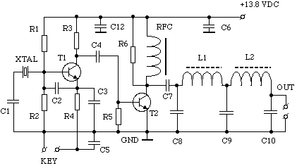
C1 = 47PF : C2, C3 = 1500PF : C4 = 0.01mfd : C5, C7 = 0.1mfd : C6, C12 = 0.047mfd : C8, C10 = 820PF : C9 = 1500PF : R1, R2 = 5K1 : R3, R5 = 100R : R4 = 180R : R6 = 1K2 : RFC = 22 MICROHENRIES (APPROX) : L1,L2 = 2.2 MICROHENRIES (21 TURNS ON T50-2) : T1 = 2N2369A : T2 = CB OUTPUT TRANSISTOR (2SC1237 OR SIMILAR) : XTAL 3.579MHZ (CHEAP COLOUR TV CRYSTAL) OR 3.560MHZ (QRP CW FREQUENCY)
This simple circuit will give about 1.2 Watts of output when powered from a 13.8VDC supply. If you don't have a 2SC1237, try any other 12V CB radio output transistor 2SC1969, 2SC1307 etc. The value of RFC is not critical, 10 turns on a high permeability ferrite toroid core works fine. I used a DPDT switch for the RX/TX switching, one pole for the aerial (antenna), the other pole to switch the 13.8V supply.