Friday 11 March 2011

AM/FM/SW active antenna


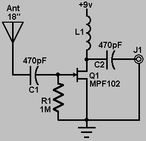
This circuit shows an active antenna that can be used for AM, FM, and shortwave (SW). On the shortwave band this active antenna is comparable to a 20 to 30 foot wire antenna. This circuit is designed to be used on receivers that use untuned wire antennas, such as inexpensive units and car radios. L1 can be selected for the application. A 470uH coil works on lower frequencies ( AM ). For shortwave, try a 20uH coil. The unit can be powered by a 9 volt battery. If a power supply is used, bypass the power supply with a .04uF capacitor to prevent noise pickup. The antenna used on this circuit is a standard 18" telescoping type. Output is taken from jack J1 and run to the input on the receiver.

Micro Power AM Broadcast Transmitter


In this circuit, a 74HC14 hex Schmitt trigger inverter is used as a square wave oscillator to drive a small signal transistor in a class C amplifier configuration. The oscillator frequency can be either fixed by a crystal or made adjustable (VFO) with a capacitor/resistor combination. A 100pF capacitor is used in place of the crystal for VFO operation. Amplitude modulation is accomplished with a second transistor that controls the DC voltage to the output stage. The modulator stage is biased so that half the supply voltage or 6 volts is applied to the output stage with no modulation. The output stage is tuned and matched to the antenna with a standard variable 30-365 pF capacitor. Approximately 20 milliamps of current will flow in the antenna lead (at frequencies near the top of the band) when the output stage is optimally tuned to the oscillator frequency. A small 'grain of wheat' lamp is used to indicate antenna current and optimum settings. The 140 uH inductor was made using a 2 inch length of 7/8 inch (OD) PVC pipe wound with 120 turns of #28 copper wire. Best performance is obtained near the high end of the broadcast band (1.6 MHz) since the antenna length is only a very small fraction of a wavelength. Input power to the amplifier is less than 100 milliwatts and antenna length is 3 meters or less which complies with FCC rules. Output power is somewhere in the 40 microwatt range and the signal can be heard approximately 80 feet. Radiated power output can be approximated by working out the antenna radiation resistance and multiplying by the antenna current squared. The radiation resistance for a dipole antenna is 80*pi^2*(length/wavelength)^2 which yields about 0.2 ohms for a 3 meter dipole at a frequency of 1.6 MHz. Radiated power at 20 milliamps is about I^2 * R = 80 microwatts and for a grounded system with a single element whip antenna, the radiated power is about half that, or 40 microwatts.
Original scheme edited by Bill Bowden, http://www.bowdenshobbycircuits.info