Tuesday 22 February 2011

HAM BAND VFO


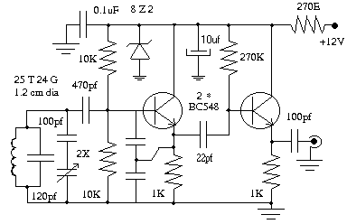
Variable frequency oscillator uses two numbers of BC548. For 40 meter band VFO oscillates form 2.567 MHz to 2.667 MHz which on mixing with 4.43 MHz generates 7.0 MHz to 7.1 MHz. If you have a frequency meter it is easy to calibrate the VFO, otherwise connect a 2J gang condenser in parallel with VFO coil and adjust it to receive ham stations. VFO is fixed inside a small aluminum box.

VFO - Variable frequency oscillator

2-BAND VFO FOR 80 AND 40 METERS

This project assumes you have built a functioning Simplest Ham Receiver and can solder components to a circuit board. Adapted from a schematic diagram in the 1993 ARRL Handbook, this VFO permits continuous user-selected tuning-range portions of about 50kHz on the 40 meter band and 30kHz on 80 meters. There are MANY designs possible, but this one was chosen because:

-- it uses the same power supply as the receiver (6-8V);

-- it demonstrates use of bipolar transistors as varactor diodes, which enables a simple cheap potentiometer to be used for tuning instead of a hard-to-find and probably expensive variable capacitor;

-- frequency range is easily changed by merely adjusting slugs on coils;

-- instead of two bands, covering larger portions of a single band is easily done; and

-- it's buildable and it works.

Decimal capacitance values are in microfarads (uF); whole-number capacitance values are in picofarads (pF or uuF).

Most general-purpose transistors will probably work in this circuit instead of those shown; back-to-back diodes can of course be tried instead of the 2N3053's.

L1: 4.6-8.5 uH adjustable RF coil (Miller #23A686RPC).
L2: 2.4-4.1 uH adjustable RF coil (Miller #23A336RPC). Miller #23A226RPC will also work.
Above coils are available from Circuit Specialists; another option that works well for L1 is the Miller #4204 5-12uH Adjustable RF Choke available from Ocean State Electronics. See Suppliers.
S1: DPDT miniature toggle switch.

Construction and Operation: First breadboard the circuit on a prototyping board to make sure it functions properly before soldering. Place the breadboarded (unsoldered) VFO in close physical proximity to the receiver, turn on the receiver, attach a mid-band-of-interest 80-meter crystal to the receiver's oscillator and tune the receiver to 80 meters. Apply power to the VFO and adjust its 80-meter coil slug until a loud signal is heard. Adjust slug to zero-beat the signal when the VFO's tuning pot is at mid-position . Make sure the VFO's switch is set for the right band! Check the VFO's tuning range by using crystal frequencies at either side of mid-band in the receiver's oscillator section. The range should be about 30 kHz.

Repeat calibration procedure for the 40-meter band - tuning range should be about 50kHz. To make a VFO that covers larger segments of just a single band, use two adjustable coils and capacitors of the same values for that band (or switch the coils between one appropriate capacitance for that band), then tune each coil for the appropriate band segment.

When the breadboarded VFO is working on both bands, go ahead and solder it together on a small experimenter's circuit board. (If you feel confident, skip the protoboard stage and solder the components to the circuit board.) Other construction techniques such as "dead bug" can be used. To minimize noise and avoid overloading, mount the switch and potentiometer on a small grounded metal panel (half an aluminum chassis box serves well) so that the VFO's circuit board is close to this panel. Do NOT enclose the VFO - leave it exposed! Like the receiver's crystal oscillator, the VFO signal output is not physically wired to the receiver; merely position the VFO as close to the receiver's L2 as you can. Be sure you have easy access to the switch, tuning pot, and (if you are using one) the Audio Q-Multiplier control knobs. Don't remove the receiver's crystal oscillator - it comes in VERY handy as a calibration source for adjusting and changing the VFO's frequency and can still function as the receiver's "emergency" tuning section. Note: the function of the receiver's tuning cap (C2) is actually that of a "preselect" that gets the receiver in the right band for the VFO's tuning function, as well as for the crystal oscillator's function as a "fixed-frequency" tuning device.

Build an Indoor FM Antenna With These Plans


The easiest way to improve your FM reception is to build an indoor FM antenna, instead of using your FM stereo’s internal FM antenna. This indoor FM antenna is easy to build, and cheap. It works every bit as good as other FM antennas that you can buy for as much as $100.

In order to build this indoor FM antenna, all you need is two 3/8” dowel rods 48” long, 10 ft. of 20 ga. wire, and some 75 ohm RG-59 or RG-6 coax (for TV’s). All of this can be picked up at your local hardware store. However sometimes hardware stores don’t have dowel rods 48”. If you can’t find any that long, you can always take two 36” dowel rods and tie them together with cable ties to the correct length.

This FM antenna is what is called a Full Wave Loop antenna. The diagram below shows the design of this indoor FM antenna:

build-indoor-fm-antenna-plans

The red is the wire, which is to be 30” on each side. The brown represents the 3/8 inch dowel rods. Also notice that the coax is fed from the side. This is not necessary, as typically full wave loops are fed from the bottom. I was interested in receiving one particular station that transmits a vertically polarized signal. Almost all FM stations transmit circularly polarized, which is both vertical, and horizontal polarization. Also feeding the Fm antenna from the side seemed to be a stronger, more reliable means of connecting the coax to the FM antenna.As far as construction of the FM antenna, the first thing to do is cut 4 inches off each dowel rod. This will then make each dowel rod 44 inches long. Next cut a slit aprox. ½ inch on each end of the dowel rods. These slits will be how you mount the wire to the dowel rods of your FM antenna.

Here is a photo of what I am talking about:

build-fm-antenna-plans

This not only shows the slot cut in the dowel rod, but also the wire, as well as the use of a cable tie to secure the wire to the end.

On the last end, where we will attach the coax to the FM antenna, put both ends of the wire into the slot leaving about an inch extending past. Next strip off the insulation and attach one end of the loop to the center conductor of the coax, and the other end of the loop to the shield of the coax.

Here is a photo of the coax being attached to the FM antenna.

build indoor fm antenna plans

Next, secure the coax to the dowel rods with it coming off the bottom dowel rod. Lastly, take a couple of cable ties and put one on the top of the vertical dowel rod to create a loop to attach a string to hang the FM antenna.

The photo below shows the completed FM antenna:

build indoor fm antenna plans

http://www.mikestechblog.com/joomla/misc/54-fm-antenna/130-build-indoor-fm-antenna-plans.html?start=1

Monday 21 February 2011

CHEAP AND EASY TO BUILD 2 METER ANTENNAS


Interested in ultra low cost 2 meter antennas that are easy to build using cheap parts; that require no tedious matching and adjusting; that are almost invisible; that are portable, compact, quickly assembled; and that can be converted into a beam? These antennas are somewhat based on the "V" designs in other projects on this site.

They include the Ultra-simple wire version in figure 1
The Table Top version in figure 2
The 2 element beam version in figure 3

Fig. 1 Ultra-simple "wire" version above made on an SO-239 connector.Designed for hanging from any handy support and can be hung from trees, used inside motel rooms or as a "stealth" antenna.


Fig 2. Table top "wire" version above using a dowel or other simple base.Upper and lower elements must be self supporting. Use aluminum or copper tubing. Disregard the reference to the upper insulator in figure 2

Fig 3. Yagi or Beam version above


This is a variation of the designs above.By adding the extra reflector element about 16 inches behind the driven element and increasing it's length to 20 inches each side (5%), some gain can be realized! According to the article, this version had not been tested but should work with a bit of experimentation. It's no more than a standard dipole with a reflector added to come up with a 2 element yagi with all elements bent forward at a 90 degree angle.

CONSTRUCTION NOTES AND TIPS

In all of these designs, please note that the center conductor from the coax connection is connected to the element in the "down position". According to the article from which these designs were taken, this helps in adjusting swr!

Simply change the angle and or trim each half a very small amount for best swr. Remember on these antennas that the driven elements have to be insulated from each other and also their support.

The beam version can be made in a "T" shape with an insulated boom between the driven element and reflector and the "T" portion for the support mast. Small diameter PVC would be a good choice.You will have to use your ingenuity for the mounting of the elements to the support so the antenna will maintain the approximately 90 degree configuration. Experiment.

An alternate version of each antenna can be built with all elements either vertical or horizontal instead of in the form of a sideways “V”.These designs can be used from HF up thru 440 or above with a little experimentation.Just dig out that old formula you should have learned for a starting point for the lengths......468/freq = half wave dipole (driven element) and add 5 percent to the length for the reflector.

The spacing should be a little less than .25 wave lengths from driven to reflector.(According to the article, using a director and driven element arrangement would cause problems with a poor match and the spacing would be a lot closer.)Using an MFJ 259b or equal would help with tuning the antenna for your particular choice of frequency, but if you're not that lucky, then just use the old swr meter and very low power while testing. As always, start with longer elements and trim down. It is very difficult to add length!

250mW FM transmitter


A very simple FM transmitter electronic project can be designed using this circuit diagram . This FM transmitter electronic project works in FM band and it has a transmission power around 250mW ( thing that make it to work at above hundred meters ) . This FM transmitter electronic circuit is very simple and is based on some common transistors and electronic parts .
T1 transistor can be a BC107, BC171 or equivalent , and is used as an small audio preamplifier that amplify the audio signal from the microphone . Adjusting the R2 variable resistor, audio signal level from the input ( microphone ) can be adjusted until will be delivered to the T1 preamplifier (an over amplified signal applied to T1 can produce an overmodulation) . From T1 , signal is delivered to T2 which form an Hartley oscillator (frequency of this oscillator depends of C8,C9 and L1) .

The transmitter frequency oscillator works in FM band 87.5-108 MHz and can be set , adjusting C8 capacitor and L1 coil . L1 coil must have four turnings on a 0.8-1 mm cylinder support with a 6 mm diameter (space between each wire must be around 1 mm ) .Antenna used for this project can be a simple telescopic antenna or a 60-70 mm Cu wire .
This electronic project can be powered from a wide range input voltage from 9 to 12 volts Dc ( but can be used even a 18 volts DC .

simple FM transmitter electronic project circuit using transistors

HF VHF UHF active antenna electronic project


A very simple and efficiency active antenna electronic project can be designed using this electronic schematic circuit that is based on transistors. This active antenna electronic project is useful for a wide range of RF frequencies covering three RF bands HF , VHF and UHF . This simple active antenna is designed to amplify signals from 3 to 3000 MegaHertz, including three recognized ranges: 3-30Mhz high-frequency (HF) signals; 3-300Mhz veryhigh frequency (VHF) signals; 300-3000MHz ultra-high (UHF) frequency signals.

This HF VHF UHF active antenna contains only two active elements : Q1 (which is an
MFE201 N-Channel dual-gate MOSFET) and Q2 (which is an 2SC2570 NPN VHF silicon transistor). Those transistors provide the basis of two independent, switchable RF pre-amplifiers. Two DPDT switches play a major role in this circuit , switch S1 used to select one of the two pre-amplifier circuits (either HF or VHF/UHF) and switch 2 is used to turn off the power to the circuit, while coupling the incoming RF directly to the input of the receiver.

S2 is useful to give to receiver nonamplified signal access to the auxiliary antenna jack, at J1, as well as the on-board telescoping whip antenna.This circuit must be powered from a simple 9 volt DC power circuit ( or a 9 volts battery) and is very useful for use as an indoor antenna .

HF VHF UHF signal booster active antenna electronic project

Sunday 20 February 2011

HF Dipole


A very basic program for calculating the length of each leg of a 1/2 wave wire dipole antenna. Program good for 1 - 500 MHz, although intended for MF - HF useage. This app does nothing more than the standard 468/freq (MHz) type calculations. It was written for DOS many years ago and ported to Windows. The output shows the 1/2 wavelength and 1/4 wavelength design wire length in feet and meters. This app is probably of no help to experienced antenna designers.

Style: GUI, File size: 46K, zipped, 22K.

Update : Minor improvements made Feb 9, 1999

Current Version is:  2 / 9 / 1999

Download the hf_dipole.zip file

NPN DC-BIAS


This application calculates the various voltages and currents of a simple voltage divider bias NPN bipolar transistor amp. The following is calculated: IB, IC, IE, VE, VB, VC, VCE and detection of Saturation or Cutoff. The user can alter the VCC, VBE, transistor beta and any of four resistor values R1, R2, RC and RE by picking the transistor value from a standard-value resistor table or manually entering the value. The schematic illustrates some of the voltage measuring points on the transistor schematic. This app is in final BETA.

Style: GUI, File size: 73K, zipped, 32K.

Current Version is:  16 / 04 / 1999

Download the nbias.zip file

Resonator


This application calculates the inductor and capacitor values for the tank circuit of a simple bipolar transistor RF amp. The basic schematic is shown above. Enter the center frequency plus the inductive/capacitive reactance you desire and press the Calculate button to calculate the necessary inductance and capacitance for L and C respectively.

Style: GUI, File size: 50K, zipped, 21K.

Current Version is:  1 / 23 / 1999

Download the resonator.zip file

HF Dipole


A very basic program for calculating the length of each leg of a 1/2 wave wire dipole antenna. Program good for 1 - 500 MHz, although intended for MF - HF useage. This app does nothing more than the standard 468/freq (MHz) type calculations. It was written for DOS many years ago and ported to Windows. The output shows the 1/2 wavelength and 1/4 wavelength design wire length in feet and meters. This app is probably of no help to experienced antenna designers.

Style: GUI, File size: 46K, zipped, 22K.

Update : Minor improvements made Feb 9, 1999

Current Version is:  2 / 9 / 1999

Download the hf_dipole.zip file

Universal Diplexer


Universal Diplexer calculates the inductance and capacitance values for a Bridge-Tee diplexer based upon a chosen superhet receiver intermediate frequency. The diplexer is the Joe Reisert, W1JR popularized design discussed under Diplexer Topics on this web site. The user inputs an IF and presses the Calculate button to have the capacitor and inductor values given in pF and uH respectively. The diplexer schematic is included in the application. Note that the this is for the Q = 1 version of the Bridge-Tee Diplexer.

Style: GUI, File size: 49K, zipped, 22K.

Current Version is:  1 / 19 / 1999

Download the diplexer.zip file

Toroidal ferrite cores


Ferrite is used to calculate the number of turns required on toroidal ferrite cores to achieve the desired millihenry-value inductance. 15 different ferrite toroids are included in this application. This program will calculate the winding data for an inductance range of 0.001 to 27 millihenries.

Style: Console, File size: 64K, zipped, 31K.

Bug Fixes: Thanks to PA3CKR for the bug report; fixed Jan 19/99.

Current Version is:  1 / 19 / 1999

Download the ferrite.zip file

PI Filter Designer


PI Filter Designer is a simple 3 element 50 ohm input and output impedance pi filter designing application. This program allows the user to design simple lowpass filters by selecting from a variety of standard capacitor values either empirically or to suit what you have on hand. The filter 3 dB cutoff frequency and required L1 inductance are automatically calculated and displayed. In addition, the user may select an additional capacitor value to put in parallel with both caps C1 and C2. In this app XL = XC = 50 ohms impedance. No other impedances can be calculated with this program.

Style: GUI, File size: 47K, zipped, 22K.

Current Version is:  1 / 14 / 1999

Download the pifilter.zip file

Coil Builder_99


CoilBuilder_99 is a powdered iron inductor winding application. Enter desired inductance, select core size and mix and press the Calculate button to determine the correct number of windings for your inductor. Data is also given showing, core color, permeability, frequency range, AL value and maximum number of turns versus wire guage for the chosen core size. Encompasses 12 different core sizes and 8 different mixes of powdered iron. Calculated results can be stored on a disk file or printed out.

Style: GUI, File size: 90K, zipped, 44K.

Bug Fixes: Some missing AL values for # 7 material added April 24/99. K6WHP's superior version is linked below.

Current Version is:  4 / 24 / 1999

Download the CB99.zip file

SQUARE WAVE OSCILLATOR

555SquareWaveOsc
555SquareWaveOsc
A square wave oscillator kit can be purchased from Talking Electronics for approx $10.00 . It has adjustable (and settable) frequencies from 1Hz to 100kHz and is an ideal piece of Test Equipment. 

Friday 18 February 2011

Simple 7 MHz QRP CW Rig

This is the schematic of my very first solid-state 7 MHz QRP CW transmitter.

It requires less than 10 parts.  A heatsink for the transistor is a must.  The 1000 pF variable is adjusted for maximum brilliance of
the lamp. DX on this rig was ~1000km (VU2SL in Valsad).

source: http://nandustips.blogspot.com/2011/02/simple-7-mhz-qrp-cw-rig.html

Marathon - A low power transmitter for 136 kHz

As is common on LF, I usually run high power on 136 kHz (400 watts). But, in May 2001, I started wondering whether the 136 kHz band would be suitable for low power operation (i.e. operating with a TX power output of just 5 watts). It certainly seemed unlikely because of the poor antenna efficiency achievable at a wavelength of 2200 m, when using an antenna just a few tens of metres in length.

But I decided to build a QRP TX for LF, and give it a try! The Marathon LF TX to be described uses: a FET VFO; FET buffer; 2N2222 amplifier + BC212 keying transistor; 2SC2166 driver; and a pair of 2SC2166 transistors in parallel.On the first morning of operation, I made three QSOs using this little TX. None of the QSOs was pre-arranged. The first contact was with Tom G3OLB in Devon - 97 km away. I was so excited that it was hard for me to maintain control of the morse key! But I managed to rattle out Tom's 599 report, and was surprised and delighted to receive my 569 report from Tom. After my QSO with Tom, I worked G3YXM (105 km) and G8IK (101 km) - all using 5 watts RF to my simple 12 m vertical (no top loading). One week later, I worked John G4CNN (Caversham, Berkshire) for my best QRP DX, at 122 km.I believe that a simple low power transmitter for 136 kHz would make an excellent club project, with the very real prospect of not just making LF QSOs across town - but over significant distances too!


VFO
The 50 pF tuning capacitor provides a tuning range of 10 kHz - enough to cover the 135.7-137.8 kHz amateur band, and yet also act as a useful source when 'searching' for antenna resonance, or measuring antenna bandwidth. The VFO drives a very effective FET buffer which presents the VFO signal to the driver stages.  (For improved voltage stabilisation, see the section 'Updates & feedback from other constructors' below.)

4.7 mH RF chokes work very well in this circuit.  In the UK, suitable RF chokes may be obtained from Maplin (light green body, 50 ohms DC resistance, of rather poor construction which is prone to failure) and Sycom (brown body, 25 ohms DC resistance, of robust construction).

VFO Circuit

PRE-DRIVER
The pre-driver stage uses an untuned 2N2222 common emitter amplifier, keyed by a BC212 PNP transistor. In my experience, many QRP TX designs fail to provide adequate shaping of the keying waveform. To reduce the likelihood of transmitting key clicks, the keying circuit in the Marathon provides a rise time of  3 ms, and a fall time of  6 ms. The result is a very pleasant T9 note.

DRIVER
The keyed signal is coupled via a 0.1 uF capacitor to the 2SC2166 driver transistor.  The gain of this stage is set by the 1200 ohm feedback resistor.   For some brands of 2SC2166, you may need to increase the gain of this stage by increasing the feedback resistor to 4700 ohms.  The drive level to the PA transistors is set by adjusting the emitter resistor, Rx.  If variable output power is required, a variable resistor of 250 ohms may be used in place of Rx.  The driver transformer, T1, is wound on a 25 mm OD 3C85 ring core, which has been found to provide excellent characteristics in LF transformer applications. An alternative core material is 3C90.

Pre-driver & Driver Circuit

PA
The PA uses two 2SC2166 transistors connected in parallel. Rx in the driver stage should be set so that, on key down, each PA transistor draws 600 mA. This can be checked by measuring the voltage across one of the 1 ohm emitter resistors: 600 mV corresponds to a current of 600 mA. To reduce the PA emitter current, increase the value of Rx in the Driver stage.  The gain of the PA is set by the 470 ohm resistor.   For some brands of 2SC2166, you may need to increase the gain of this stage by increasing the 470 ohm resistor to 1200 ohms.  The PA transistors will require a heatsink. Note that the tab of the 2SC2166 is internally connected to the collector, so be sure to use an insulating kit!
The PA transformer, T2, uses a 25 mm OD 3C85 ring core.

DC Switching and PA Circuit

Construction
Because the VFO runs at the TX output frequency, some 'pulling' of the VFO frequency might be expected on key down.  The degree of VFO shift will depend upon output power, and the magnetic coupling between the VFO coil and T2/L1/L2.   This effect can be minimised, through effective screening between the VFO and the PA; and single-point earthing of all stages.   The use of ring cores for L1 and L2 would also help (see 'Constructing the low pass filter inductors' below).Those with lots of experience of building homemade rigs will have no trouble building the Marathon into a smart equipment case. 

Those with less experience would, perhaps, benefit by starting with a simpler approach. A prototype version can be constructed quickly on copper clad board using 'ugly construction' techniques. For such an approach, start by fixing some off-cuts of copper clad board to a piece of wood or 'chipboard'. (Prior to fitting the copper-clad board, be sure to remove any oxidation using metal polish, followed by a rinse with soap and water.) Odd scraps of aluminium sheet, or lids from tobacco, confectionery or biscuit tins can be used as the front and rear panels by screwing them to the front and back edges of the chipboard. Start by getting the tuning capacitor; antenna sockets; TX/RX switch; NET switch; 12 v connector; and PA transistors/heatsink mounted in convenient positions, and in relation to their position in the circuit diagram.


The rest is easy: solder those components needing a connection to earth directly to the copper-clad board; and solder the remaining components directly to one another. Don't worry too much about lead lengths; but be sure to provide enough spacing between components to prevent short circuits, and to allow voltage measurements to be made during testing. To support larger components, high value resistors can be soldered to earth at one end, and the other end to the component - a sort of poor man's 'insulated' terminal post.  The bird's nest in the picture below worked just fine!

qrptx_1.jpg (52008 bytes)

For more information about ugly construction techniques, click here.

Constructing the low pass filter inductors

First layer Second layer

L1 and L2 are 55 uH inductors, wound on separate formers and mounted at 90 degrees to each other. For each coil former, I used a 50 mm length of 22 mm outside diameter PVC pipe, purchased from a plumber's merchant. (Note that such pipe is often identified by its internal diameter, rather than its outside diameter.) The coil was wound with wire salvaged from a 5 m length of internal telephone cable - the type used for permanent wiring along skirting boards etc..  This type of wire is plastic-coated, having an overall diameter of about 0.9 mm. First, wind a single layer of 33 turns on the 22 mm pipe, and hold the turns in place using one layer of insulating tape. Then wind a second layer of 27 turns, centrally over the top of the first layer, and hold the turns in place with insulating tape. To complete the coil, solder the end of the first winding (B) to the start of the second winding (C).
The inductance may be checked using a dip oscillator: when a 270 pF capacitor is connected across the 55 uH inductor, resonance should occur at about 1.3 MHz.

Alternatively, L1 and L2 may be wound on ring cores, using Amidon type T130-2 cores (coloured red and grey).  60 turns of telephone cable wire (about 2 m in length) will do the job nicely.

Winding the transformers

T1 & T2

The driver transformer, T1, and the output transformer, T2, are wound on 25 mm OD 3C85 ring cores. The wire gauge is not critical: hook-up wire capable of carrying one ampere would be fine.  For T2, it helps if the wires are colour-coded.  I used telephone cable wire for both T1 and T2.  For T1, wind fourteen closely-spaced turns in a single-layer on the toroid, and hold them in place using small cable ties, or insulating tape. Then wind seven turns, centrally over the first winding, and retain in place.
For T2, twist three wires together at about one twist every 15 mm. Wind twelve turns on the toroid, and label each of the three wires at the start of the winding with the identification numbers 1; 3; 5.  Then label the other end of each wire with 2; 4; 6 respectively. Refer to the PA circuit diagram to ensure correct installation. The number of turns is not critical in this design: during testing, I found no difference in performance between a transformer of 10 turns, and another wound with 14 turns.

Pin-out Diagrams

Pin-out diagrams

Putting the Marathon in a box

The original 'bird's nest' version has proved to be effective and stable, but I wanted to build a more rugged transmitter - something that I could take out portable, if required.

Consequently, a second Marathon transmitter was built using ugly construction into a small diecast box measuring 150 mm  (length)  x  50 mm  (height)  x   80 mm (depth).  To maintain adequate screening between the VFO and the PA sections, it was necessary to install the PA transformer (T2) and low pass filter ring cores (L1 & L2) in a separate tin plate box, mounted on the lid of the diecast box.  Note that, for the tin plate box. I chose to use an 'Altoids' peppermint box - a favourite project box used by many QRPers!
A sensitive RF probe

A sensitive RF probe is very useful in a situation where an oscilloscope is not available. This design allows measurement of the peak-to peak amplitude of an RF signal in the 100 kHz to the VHF range at up to 50 volts P-P. 50 Volts P-P is approximately 14 volts RMS. The 50 volt P-P limit is due to the 60 volt breakdown rating of the diodes

The upper frequency range limit of the probe is due to the length of the ground wire and the stray junction capacitance of the germanium diodes. It is designed for use with a high impedance DC voltmeter, or VOM. Instruments with FET inputs are preferable.Avoid using a long ground lead. Keep the ground lead as short as possible, and attach it as close as possible to the ground point of the circuit under test.

A thirty-six (36) inch length of RG-174 coax is recommended for the probe’s cable. RG-174 is well suited for this task because of its small diameter and flexibility. Also, #16-#18 guage insulated stranded hook-up wire can be used. Twist the wires together.

The RF probe is a charge pump. The peak crest value of a signal is stored in the stray capacitance of the coaxial cable. The stray capacitance of the cable is about 50 pF. The 50 pF capacitance of the cable, and the 10 mega-ohm input impedance of an FET VOM implies a DC filter time constant of 500 m Seconds, Accurate measurements are possible at frequencies as low as 100 kHz.

Noticeable errors occur at low signal levels because of the forward bias drop of the diodes. Assume a total diode voltage drop of about 0.3 volts.If a standard 20KW /Volt meter is used, then you may have to add a 1000 pF capacitor across the input of the VOM to improve DC filtering. Expect more circuit loading effects, and an increase in the probe’s lower cut-off frequency.

Thursday 17 February 2011

FM super regenerative Receiver


clip_image002

We also wind the coils ourselves. The oscillator coil is made from five turns of 0.8 mm (ideally, silver plated) copper wire on a diameter of 8 mm. Short connections are essential, especially to the tuning capacitor: we soldered a trimmer directly to the ground plane. The second coil in the circuit consists of 20 turns of 0.2 mm enamelled copper wire wound on a 10 kΩ resistor. The rest of the circuit is constructed as shown in Figure

The antenna should not be too long, as otherwise the circuit may cause interference: the superregenerative circuit is also a transmitter! Nevertheless the circuit is very sensitive and operates perfectly satisfactorily using a 10 cm length of wire for an antenna. The headphones should ideally have an impedance of at least 400 Ω. The circuit will work with 32 Ω stereo headphones, but the output will not be as loud.

10-m rectangular loop antenna.


clip_image002[1]

With the large number of operators and wide availability of inexpensive, single-band radios, the 10-m band could well become the hangout for local ragchewers that it was before the advent of 2-m FM, even at a low point in the solar cycle.

This simple antenna provides gain over a dipole or inverted V. It is a resonant loop with a particular shape. It provides 2.1dB gain over a dipole at low radiation angles when mounted well above ground. The antenna is simple to feed— no matching network is necessary. When fed with 50-Ù coax, the SWR is close to 1:1 at the design frequency, and is less than 2:1 from 28.0-28.8 MHz for an antenna resonant at 28.4 MHz.

The antenna is made from #12 AWG wire (see Fig ) and is fed at the center of the bottom wire. Coil the coax into a few turns near the feedpoint to provide a simple balun. A coil diameter of about a foot will work fine. You can support the antenna on a mast with spreaders made of bamboo, fiberglass,

wood, PVC or other nonconducting material. You can also use aluminum tubing both for support and conductors, but you’ll have to readjust the antenna dimensions for resonance. This rectangular loop has two advantages over a resonant square loop. First, a square loop has just 1.1 dB gain over a

dipole. This is a power increase of only 29%. Second, the input impedance of a square loop is about 125 W. You must use a matching network to feed a square loop with 50-Ù coax. The rectangular loop achieves gain by compressing its radiation pattern in the elevation plane. The azimuth plane pattern is slightly wider than that of a dipole (it’s about the same as that of an inverted V). A broad pattern is an advantage for a general- purpose, fixed antenna. The rectangular loop provides a

bidirectional gain over a broad azimuth region. Mount the loop as high as possible. To provide 1.7 dB gain at low angles over an inverted V, the top wire must be at least 30 ft high. The loop will work at lower heights, but its gain advantage disappears. For example, at 20 ft the loop provides the same gain at low angles as an inverted V.

Wednesday 16 February 2011

A short wave regenerative receiver


Ing. Ramón Vargas Patrón rvargas@inictel.gob.pe

Sensitivity and selectivity are the major concerns of a short wave enthusiast when he looks up for a receiver. Commercial communications models with superhet circuitry surely satisfy his requirements, but these are expensive. He would rather go for a homebrewed radio, being a regenerative receiver an affordable choice.

I'm also a short wave listener and for some time I used my family's MW and SW tube radio, Philips brand. Then I switched to a Sony ICF-7600 with ceramic filters in the IF stages. High selectivity was attained with this radio receiver.


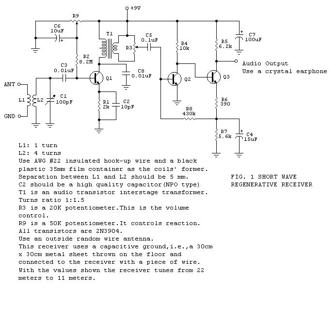
I then discovered how much fun it was to build radios in my spare time, having tested a variety of designs available in books and on the web. Finally, I managed to make my own designs. One of them is shown in Fig. 1. It is a nice performer and will tune from the 22 meter international broadcasting band down to the 11 meter band.

It is best that the 100 pF variable capacitor be a vernier type. Tuning will be easier this way.

Q1 is the amplifier-detector and along with its associated circuitry forms a common collector Colpitts oscillator that not actually oscillates: it operates as a regenerative amplifier, with R9 as the reaction control. In achieving this result, the transistor's input capacitance plays an important role. The oscillating mode is employed when copying CW or SSB. Otherwise, the stage should be left very near the threshold of oscillation for maximum sensitivity and selectivity.

Q2 and Q3 form a high gain audio amplifier and ample volume should be expected at the output. This is why a volume control has been included in the circuit. A high impedance crystal earphone should be used at the output.

A Quick and Simple 2 Meter Ground Plane Project!

If you are just getting experience in building antennas or you are an old pro,here is a simple and fun project! This antenna is perfect for those hams living in the primary coverage area of the repeater for 2 meter use. This antenna is nothing more than the old standby "Droopy Groundplane" and can be used on any band where it's physical size does not pose a problem. Remember that the vertical radiator is 1/4 wavelength long at your operating frequency.

It has no gain but makes an excellent small antenna that can be mounted just about anywhere and with a little planning, can be used mobile on a short mast from the bumper!! Adding a small attachment loop at the tip of the radiator will enable it to be suspended from above for inside use.

The vertical element and radials can be made of #12 copper wire or welding rods, coat hanger, etc. The vertical radiator (A) should be soldered to the center connector of the SO239.The four base radials (B & C) and (D & E) can be soldered or bolted to the SO239 mounting holes using 4-40 hardware. The four base radials then should be bent downward to a 45 degree angle.

The antenna can be mounted by clamping the PL259 to a mast or even passing the coax through a 3/4 ID PVC pipe and compression clamping the PL259. Either way let your creativity work for you. If you plan on mounting it outside,  apply RTV or sealant around the center pin and PL259, and TAPE WELL,  to keep water out of the coax.

Make each radial a 1/4 wave of your desired xmit frequency. Sometimes it helps to add a little extra length to the radials and radiator. This will give you some adjusting room when you adjust the SWR.(If adjustment is needed, clip all radials equally about 1/8 inch at a time while checking SWR, USING LOW POWER). Center the lowest swr on your transmit operating frequency.

Example Calculation:

Freq (mhz)       146
A (inches)         19 5/16 (Note "A" length is to the SO-239 insulator but not critical)

B THRU E (INCHES)   20 3/16

LENGTHS FROM FORMULA ( 234/FREQ MHZ) + 5 % LONGER FOR RADIALS
TRY ONE ON 440 or other bands USING SAME FORMULA AND CONSTRUCTION TECHNIQUES!

ENJOY AND EXPERIMENT!

DON'T TRY IT ON 75 METERS MOBILE......IT' A LITTLE LONG FOR MOST BRIDGES, OVERPASSES, POWER LINES ETC!!!!

Simple Morse Practice Oscillator Circuit


This will be my next homebrew project, a morse practice oscillator circuit. 9W2AZV and I are going to build this as we are preparing ourselves to perfect our Morse code sending/receiving skills.

In the spirit of amateur radio/ham, we will homewbrew the equipment using easily obtainable parts from our nearest electronic stores.

Here’s the circuit

osc.jpg

IC RADIO

ICradio

This circuit contains an IC but it looks like a 3-leaded transistor and that's why we have included it here.The IC is called a "Radio in a Chip" and it contains 10 transistors to produce a TRF (tuned Radio Frequency) front end for our project. The 3-transistor amplifier is taken from our SUPER EAR project with the electret microphone removed. The two 1N 4148 diodes produce a constant voltage of 1.3v for the chip as it is designed for a maximum of 1.5v. The "antenna coil" is 60t of 0.25mm wire wound on a 10mm ferrite rod. The tuning capacitor can be any value up to 450p.

27MHz TRANSMITTER WITH SQUARE-WAVE OSCILLATOR

27MHzTx-SquarewaveOsc

The circuit consists of two blocks. Block 1is a multivibrator and this has an equal mark/space ratio to turn the RF stage on and off. Block 2 is an RF oscillator. The feedback to keep the stage operating is provided by the 27p capacitor. The frequency-producing items are the coil (made up of the full 7 turns) and the 47p air trimmer. These two items are called a parallel tuned circuit. They are also called a TANK CIRCUIT as they store energy just like a TANK of water and pass it to the antenna. The frequency of the circuit is adjusted by the 47p air trimmer

27MHz TRANSMITTER - 2 CHANNEL

27MHzTx-2Ch

This circuit does not use a crystal but has a clever feature of using the two push buttons to turn the circuit on when it is required to transmit. The frequency of the multivibrator is determined by the value of resistance on the base of each transistor. The multivibrator is driven directly from the supply with the forward button and via a 150k for the reverse frequency. The receiver requires a 1kHz tone for forward and 250Hz for reverse.

303MHz TRANSMITTER

303MHzTx


The transmitter circuit is made up of two building blocks - the 303MHz RF oscillator and the 32kHz crystal controlled oscillator to generate a tone so the receiver does not false-trigger. The 303MHz oscillator consists of a self-oscillating circuit made up of the coil on the PC board and a 9p (9 puff) capacitor.

PHONE TRANSMITTER – 2


This circuit has poor features but you can try it and see how it performs. It uses a PNP transistor and requires a separate antenna. It also has a supply of less than 1.9v, via the red LED. It would be better to put 2 LEDs in series to get a higher voltage. It is activated when the phone is picked up.

PhoneTransmitter-3

PhoneTx-3

PHONE TRANSMITTER


PhoneTx-1PCBPhoneTransmitter-1


The circuit will transmit a phone conversation to an FM radio on the 88-108MHz band. It uses energy from the phone line to transmit about 100metres. It uses the phone wire as the antenna and is activated when the phone is picked up. The components are mounted on a small PC board and the lower photo clearly shows the track-work.

Two transistor Radio

5-TrRadio
If you are not able to get the ZN414 IC, this circuit uses two transistors to take the place of the chip.

Tuesday 15 February 2011

Simple and Powerful FM transmitter

This simple FM Transmitter is very powerful (mean its not simple one..! but its easy to make..).  You can transmit FM signals up to 5km radius circle area using this Transmitter. I recommend to use 12V battery for supplying power. If you wish to use 12V AC-DC adapter you may want to make a very smooth DC out put using stabilizer, unless it will generate low frequency hum when listening to FM radio out put. For making L1 coil use 18SWG copper wire (about 1mm diameter) and make 7 turns(see figure 2). Use 75Ω TV cable's middle wire for antenna, It should be 2meters long(see figure 3).

figure1


Making the coil(use 18SWG copper wire or around to it)>>

figure2


Antenna(Use this cable for best results, otherwise you can use any type of copper wire(at least 2meters long))>>

figure 3


Transistor pin identification>>

Low Cost Powerful AM Transmitter (13Km)

This is a simple AM Transmitter Circuit, but Its very powerful one. It can transmit SW range signals within 13Km circular area. Use external antenna for best results. I recommend to use 12V battery as the power supply. If you hope to using 12V AC-DC adapter you may want to keep very smooth DC out put using stabilizer, unless it will generate low frequency hum when listening to radio out put.  Better to read following instructions before assembling the circuit.

>

> L1 Coil

Use 22SWG copper wire and make 10 turns, Insert a ferrite rod in to the coil. see figure 1.

>> L2 Coil
Use 22SWG Copper wire and make 10 turns. Don't use a ferrite rod. Coil diameter is 0.6 cm ( 1/4' ).
>> X-tal (Crystal)
Use 4.4333MHz crystal.

Push-pull Linear Amplifier with NE592 Driver


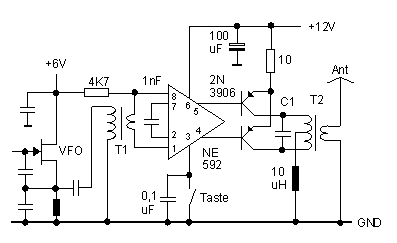
Transformer T1 matches the relatively low impedance present at the VFO FET gate to the balanced inputs of the NE592. With a unipolar power supply, it is necessary to bias both inputs to roughly one-half of Vcc. Below, we have shown both inputs tied to +6 VDC, conveniently available from the VFO. If 6 volts were not available, we would employ a scheme identical to the "IF amplifier" shown earlier, with Vcc split in half with 2 4,7K-ohm resistors in a divider configuration, applied to both inputs. Normally, stage gain is determined by the value of a resistor between pins 2 & 7. Bench tests reveal better output symmetry, however, if we replace this resistor with a 1 nF capacitor.

Approximately 8 volts of RF drive is available at pins 4&5 if we don't load it too heavily. This is sufficient to drive a pair of 2N3906 PNP transistors in push-pull to roughly 1,5 watts output with excellent efficiency. With bias provided by the NE592, the output transistors are operated in their linear region. Push-pull operation provides inherent suppression of even-order harmonics (2f, 4f, etc.), thereby simplifying our output network design (not shown). T2 is a T44-2 toroid with 5 bifilar primary turns and a single 5 turn secondary. C1 is around 270 pF (for 10 MHz), and should be adjusted to resonate the primary of T2 to signal frequency.

Fig 1: Schematic of the push-pull final (Pin designations are for the 8 pin DIP package)
{short description of image}

A tuned transform tank does not like to see a severely reactive load. An antenna tuner or some other means of cancelling reactance and transforming impedance must be employed if the load departs significantly from 50+j0 ohms. Broadband transformers, on the other hand, are inherently less sensitive to mismatch because of their low Q, but must be backed up with an effective harmonic suppression filter to achieve acceptable spectral purity. A single pi-network should do it. A low Q parallel-resonant circuit (low L, high C) was also tried, with acceptable results.