Wednesday 16 February 2011

A short wave regenerative receiver


Ing. Ramón Vargas Patrón rvargas@inictel.gob.pe

Sensitivity and selectivity are the major concerns of a short wave enthusiast when he looks up for a receiver. Commercial communications models with superhet circuitry surely satisfy his requirements, but these are expensive. He would rather go for a homebrewed radio, being a regenerative receiver an affordable choice.

I'm also a short wave listener and for some time I used my family's MW and SW tube radio, Philips brand. Then I switched to a Sony ICF-7600 with ceramic filters in the IF stages. High selectivity was attained with this radio receiver.


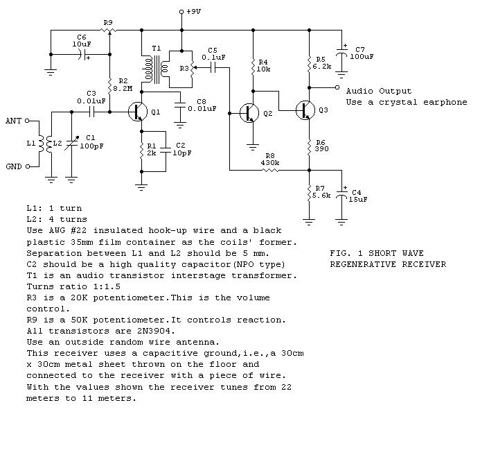
I then discovered how much fun it was to build radios in my spare time, having tested a variety of designs available in books and on the web. Finally, I managed to make my own designs. One of them is shown in Fig. 1. It is a nice performer and will tune from the 22 meter international broadcasting band down to the 11 meter band.

It is best that the 100 pF variable capacitor be a vernier type. Tuning will be easier this way.

Q1 is the amplifier-detector and along with its associated circuitry forms a common collector Colpitts oscillator that not actually oscillates: it operates as a regenerative amplifier, with R9 as the reaction control. In achieving this result, the transistor's input capacitance plays an important role. The oscillating mode is employed when copying CW or SSB. Otherwise, the stage should be left very near the threshold of oscillation for maximum sensitivity and selectivity.

Q2 and Q3 form a high gain audio amplifier and ample volume should be expected at the output. This is why a volume control has been included in the circuit. A high impedance crystal earphone should be used at the output.

A Quick and Simple 2 Meter Ground Plane Project!

If you are just getting experience in building antennas or you are an old pro,here is a simple and fun project! This antenna is perfect for those hams living in the primary coverage area of the repeater for 2 meter use. This antenna is nothing more than the old standby "Droopy Groundplane" and can be used on any band where it's physical size does not pose a problem. Remember that the vertical radiator is 1/4 wavelength long at your operating frequency.

It has no gain but makes an excellent small antenna that can be mounted just about anywhere and with a little planning, can be used mobile on a short mast from the bumper!! Adding a small attachment loop at the tip of the radiator will enable it to be suspended from above for inside use.

The vertical element and radials can be made of #12 copper wire or welding rods, coat hanger, etc. The vertical radiator (A) should be soldered to the center connector of the SO239.The four base radials (B & C) and (D & E) can be soldered or bolted to the SO239 mounting holes using 4-40 hardware. The four base radials then should be bent downward to a 45 degree angle.

The antenna can be mounted by clamping the PL259 to a mast or even passing the coax through a 3/4 ID PVC pipe and compression clamping the PL259. Either way let your creativity work for you. If you plan on mounting it outside,  apply RTV or sealant around the center pin and PL259, and TAPE WELL,  to keep water out of the coax.

Make each radial a 1/4 wave of your desired xmit frequency. Sometimes it helps to add a little extra length to the radials and radiator. This will give you some adjusting room when you adjust the SWR.(If adjustment is needed, clip all radials equally about 1/8 inch at a time while checking SWR, USING LOW POWER). Center the lowest swr on your transmit operating frequency.

Example Calculation:

Freq (mhz)       146
A (inches)         19 5/16 (Note "A" length is to the SO-239 insulator but not critical)

B THRU E (INCHES)   20 3/16

LENGTHS FROM FORMULA ( 234/FREQ MHZ) + 5 % LONGER FOR RADIALS
TRY ONE ON 440 or other bands USING SAME FORMULA AND CONSTRUCTION TECHNIQUES!

ENJOY AND EXPERIMENT!

DON'T TRY IT ON 75 METERS MOBILE......IT' A LITTLE LONG FOR MOST BRIDGES, OVERPASSES, POWER LINES ETC!!!!

Simple Morse Practice Oscillator Circuit


This will be my next homebrew project, a morse practice oscillator circuit. 9W2AZV and I are going to build this as we are preparing ourselves to perfect our Morse code sending/receiving skills.

In the spirit of amateur radio/ham, we will homewbrew the equipment using easily obtainable parts from our nearest electronic stores.

Here’s the circuit

osc.jpg

IC RADIO

ICradio

This circuit contains an IC but it looks like a 3-leaded transistor and that's why we have included it here.The IC is called a "Radio in a Chip" and it contains 10 transistors to produce a TRF (tuned Radio Frequency) front end for our project. The 3-transistor amplifier is taken from our SUPER EAR project with the electret microphone removed. The two 1N 4148 diodes produce a constant voltage of 1.3v for the chip as it is designed for a maximum of 1.5v. The "antenna coil" is 60t of 0.25mm wire wound on a 10mm ferrite rod. The tuning capacitor can be any value up to 450p.

27MHz TRANSMITTER WITH SQUARE-WAVE OSCILLATOR

27MHzTx-SquarewaveOsc

The circuit consists of two blocks. Block 1is a multivibrator and this has an equal mark/space ratio to turn the RF stage on and off. Block 2 is an RF oscillator. The feedback to keep the stage operating is provided by the 27p capacitor. The frequency-producing items are the coil (made up of the full 7 turns) and the 47p air trimmer. These two items are called a parallel tuned circuit. They are also called a TANK CIRCUIT as they store energy just like a TANK of water and pass it to the antenna. The frequency of the circuit is adjusted by the 47p air trimmer

27MHz TRANSMITTER - 2 CHANNEL

27MHzTx-2Ch

This circuit does not use a crystal but has a clever feature of using the two push buttons to turn the circuit on when it is required to transmit. The frequency of the multivibrator is determined by the value of resistance on the base of each transistor. The multivibrator is driven directly from the supply with the forward button and via a 150k for the reverse frequency. The receiver requires a 1kHz tone for forward and 250Hz for reverse.

303MHz TRANSMITTER

303MHzTx


The transmitter circuit is made up of two building blocks - the 303MHz RF oscillator and the 32kHz crystal controlled oscillator to generate a tone so the receiver does not false-trigger. The 303MHz oscillator consists of a self-oscillating circuit made up of the coil on the PC board and a 9p (9 puff) capacitor.

PHONE TRANSMITTER – 2


This circuit has poor features but you can try it and see how it performs. It uses a PNP transistor and requires a separate antenna. It also has a supply of less than 1.9v, via the red LED. It would be better to put 2 LEDs in series to get a higher voltage. It is activated when the phone is picked up.

PhoneTransmitter-3

PhoneTx-3

PHONE TRANSMITTER


PhoneTx-1PCBPhoneTransmitter-1


The circuit will transmit a phone conversation to an FM radio on the 88-108MHz band. It uses energy from the phone line to transmit about 100metres. It uses the phone wire as the antenna and is activated when the phone is picked up. The components are mounted on a small PC board and the lower photo clearly shows the track-work.

Two transistor Radio

5-TrRadio
If you are not able to get the ZN414 IC, this circuit uses two transistors to take the place of the chip.