Sunday 29 June 2014

Wideband RF Field Strength Meter


Field strength meter is extremely useful when working with RF devices. It can be used to quickly diagnose whether a transmitter circuit is working, and can be used to detect RF signals in the environment. The simplest field strength meter could be built with a tuned LC circuit and a germanium diode, just like the way of a building a crystal radio except replacing the ear piece with a high sensitivity current meter. While this approach fits the needs of most simple applications, it has a pretty narrow frequency range (~100 MHz) and requires tuning the LC circuit to the correct frequency before measurements can be made and the design can become complicated if wider frequency range tuning is desired.

Wideband RF Field Strength Meter

Another option is to use an RF detection chip. Most of such chips (from Linear Technologies, Maxim and Analog Devices) offer a very broad testing range and have much higher sensitivity and accuracy than a simple diode signal detector can offer. Here I will use Linear Technologies’ LT5534 RF detector chip as the field strength meter’s front end. Similar circuits can be build with other RF detection chips as well, depending on the types of the specific application.

LT5534 can detect RF signal from 50MHz all the way up to 3GHz, which covers most of the spectrum one typically uses. If your frequency spectrum is significantly different, you may check out the other RF detection chips the above mentioned companies offer.

The core detector circuit is almost identical to the reference design. The LM324 op-amp forms a differential amplifier with a gain of 2. The main purpose of this differential amplifier is to provide the ability to “zero” the meter reading or adjust the sensitivity of the detector. Since the differential op-amp’s output is proportional to the voltage difference between the output of LT5534 and the wiper voltage of the potential meter, we can adjust the potential meter to set the reference point (i.e. zero reading) for the environment. Also, by raising the wiper’s potential, it would take a higher output from the RF detector for the differential op-amp to register an input voltage and thus effectively lowered the sensitivity of the detector.
The output bandwidth of LT5534 is tens of MHz, since we do not care about the signal details in this particular application, the relatively low bandwidth LM324 has no impact on performance. The above circuit uses a 5V regulated power supply.

Saturday 28 June 2014

5W1.5W 88-108Mhz FM Transmitter 14MHz (20m) AM Transmitter


This transmitter is designed to transmit sound (music, speech, ...) at frequencies 88-108MHz with a frequency modulation (FM). Its RF power is about 1.5 W. The first transistor is used as an RF oscillator. Varicap allows the oscillator frequency shifting and thus its frequency modulation and frequency tuning via potentiometer. Varicap may not be the BB105, it can be BB409, BB109G, KB109G or other type. The second transistor is the power output stage. The output signal goes through a filter to remove harmonics and then it enters antenna, eg dipole or Yagi antenna (it has better directivity). Power transistor is on the heatsink with min. 100 cm2 area. Coils are air, wire diameter of 0.6 mm wound on 5 mm.

     Warning! Operating this transmitter without permission is illegal.


1.5W 88-108Mhz FM power Transmitter schematic (note: "z" means number of turns)

40 Meter QRPp Transmitter


Steve Yates - AA5TB

40m QRPp Transmitter


I built this simple, crystal controlled 40 meter CW transmitter back in 1996. It sports full break-in operation and 250 mW of output power. The final output transistor is a mighty 2N2219A. The N6WG QSL card laying against the lid is just an example of one of the many contacts I have made with this transmitter. The station was located in California and my antenna was an inverted L (bent monopole) operated against a very poor ground system (a couple of ground rods). Considering the losses in my antenna system, I thought the contact was pretty good.

My design was based on one of the late Doug DeMaw's (W1FB) designs with many of my own modifications. The rig is built into an old file box I bought at a garage sale for $1.00.s

Inside View
Inside View

Schematic Diagram

Friday 27 June 2014

SSB signal generated by phase shift


SSB signal generated by phase shift
Home SSB transmitter is a challenge to the HAM and a test to its own power. But up to now little HAM can self-make SSB transmitter, the main reason is the core components of the transmitter SSB-crystal filter and the matching crystal (such as crystal filters are equipped with 9MHz the 8998.5kHz, 9001.5kHz crystal) is difficult to purchase in the country, in this case, the phase shift method can generate SSB signals, comparing with the commonly used filter, but it has the advantages of easy make, low-cost, particularly the output frequency of VFO (should have a very high degree of frequency stability) can be directly taken as the firing frequency, it does not have to go through one or more frequency, greatly simplifying the whole circuit , the circuit is shown as the chart.

Tuesday 24 June 2014

Bipolar Junction Transistor Beta Tester


Above — Disappointed with the transistor beta testers in our common, low-cost digital multimeters, we did the logical thing; designed and built our own. This collaborative project was more an experiment with BJTs than anything else. It's about as simple a beta measurement device as you can make and still get good results. Preventing damage to our parts inventory underpins this design — the 100 Ω emitter resistor plus ~ 10 microamps of base bias keeps the IC low to help avoid smoke since most new small signal transistors have a beta of 100-400.

Ensure the correct polarity for PNP versus NPN transistors. The voltage divider targets 5 volts using a standard ~12 volt supply; I just used whatever resistors were handy and ended up with the 6K8 — 3K3 pair. VCC should be regulated. Perform the measurements with a single multimeter allowing time for stabilization.

To use: Set the potentiometer so that the voltage drop across the 10K resistor is 100 mV. Then move your DMM leads to the 100 Ω resistor and measure the beta. This device measures beta, the static gain at DC.

Measuring beta is a bit inexact since beta is affected by so many variables as follows:

  1. Beta tends to be low at low operating currents and rises and plateaus for medium currents and then falls at higher currents.
  2. Beta tends to increase with temperature.
  3. Beta is affected by the voltage between the collector and emitter -- this is a weak effect except when the voltage is very small.
  4. The beta can vary as the battery depletes in DMM beta testers.

Saturday 21 June 2014

Simple FM Receiver


Frequency modulation is used in radio broadcast in the 88-108MHz VHF band. This bandwidth range is marked as FM on the band scales of radio receivers, and the devices that are able to receive such signals are called FM receivers. The FM radio transmitter has a 200kHz wide channel. The maximum audio frequency transmitted in FM is 15 kHz as compared to 4.5 kHz in AM. This allows much larger range of frequencies to be transferred in FM and thus the quality of FM transmission is significantly higher than of AM transmission.


Here’s a simple FM receiver with minimum components for local FM reception. Transistor BF495 (T2), together with a 10k resistor (R1), coil L, 22pF variable capacitor (VC), and internal capacitances of transistor BF494 (T1), comprises the Colpitts oscillator. The resonance frequency of this oscillator is set by trimmer VC to the frequency of the transmitting station that we wish to listen. That is, it has to be tuned between 88 and 108 MHz. The information signal used in the transmitter to perform the modulation is extracted on resistor R1 and fed to the audio amplifier over a 220nF coupling capacitor (C1).

You should be able to change the capacitance of the variable capacitor from a couple of picofarads to about 20 pF. So, a 22pF trimmer is a good choice to be used as VC in the circuit. It is readily available in the market. If you are using some other capacitor that has a larger capacitance and are unable to receive the full FM bandwidth (88-108 MHz), try changing the value of VC. Its capacitance is to be determined experimentally.

The self-supporting coil L has four turns of 22 SWG enamelled copper wire, with air core having 4mm internal diameter. It can be constructed on any cylindrical object, such as pencil or pen, having a diameter of 4 mm. When the required number of turns of the coil has reached, the coil is taken off the cylinder and stretched a little so that the turns don’t touch each other.

Capacitors C3 (100nF) and C10 (100µF, 25V), together with R3 (1k), comprise a band-pass filter for very low frequencies, which is used to separate the low-frequency signal from the high-frequency signal in the receiver.You can use the telescopic antenna of any unused device. A good reception can also be obtained with a piece of isolated copper wire about 60 cm long. The optimum length of copper wire can be found experimentally.

The performance of this tiny receiver depends on several factors such as quality and turns of coil L, aerial type, and distance from FM transmitter. IC LM386 is an audio power amplifier designed for use in low-voltage consumer applications. It provides 1 to 2 watts, which is enough to drive any small-size speaker. The 22k volume control (VR) is a logarithmic potentiometer that is connected to pin 3 and the amplified output is obtained at pin 5 of IC LM386. The receiver can be operated off a 6V-9V battery.

Crystal AM Transmitter


Here is the circuit of a medium-power AM transmitter that delivers 100-150 mW of radio frequency (RF) power. At the heart of the circuit is a crystal oscillator. A 10MHz crystal is used to generate highly stable carrier frequency. Audio signal from the condenser mic is amplified by the amplifier built around transistors T1, T2 and T3. The amplified audio signal modulates the RF carrier generated by the crystal oscillator built around transistor T4. Here modulation is done via the power supply line. The amplitude-modulated (AM) signal is obtained at the collector of oscillator transistor T4.


Fig. 1: Circuit of crystal AM transmitter


Fig. 2: Oscillator coil


Fig. 3: Modulation transformer

By using matching dipole antenna and co-axial cable, the range of signal transmission can be increased. For maximum range, use a sensitive radio with external wire antenna. The circuit works off a 9V-12V battery. For oscillator coil L1, wind 14 turns of 30SWG wire round an 8mm diameter radio oscillator coil former with a ferrite bead (see Fig. 2). For modulation transformer X1, you can use the audio output transformer of your old transistor radio set. Alternatively, you can make it from E/I section transformer lamination with inner winding having 40 turns of 26SWG wire and the outer winding having 200 turns of 30SWG as shown in Fig 3.

Low-Range AM Radio Transmitter


Here is a simple radio transmitter for transmission up to 25 metres. It is basically an AM modulator whose signal can be received on the normal AM radio. It can also be used as an AM radio tester.IC 555 (IC1) is used as a free running multivibrator whose frequency is set above 540 kHz. Here the circuit is designed for a frequency of around 600 kHz. The frequency of the multivibrator can be calculated as follows:
f=1.443(R1+2R2)C1

where resistors R1 and R2 are in ohms, capacitor C1 is in microfarads, and frequency f is in hertz. This frequency can be changed by simply replacing R2 with a variable resistor or C1 with gang capacitors. But it may increase the complexity of the circuit. A condenser microphone is used for speaking.

The IC 555 multivibrator is used as a voltage-to-frequency converter. The output of the condenser microphone is given to pin 5 of IC1, which converts the input voltage or voice signal into its appropriate frequency at output pin 3. This frequency produces an electromagnetic wave, which can be detected by a nearby radio receiver, and you can hear your own voice in that radio. Note that the receiver should be AM type. If there is no noise in receiver, tune it to 600 kHz.The circuit operates off a 9V regulated power supply or a 9V battery. For antenna, connect 2-3m long wire at pin 3.

CRYSTAL AM TRANSMITTER


The LM386 is a common integrated circuit that acts as an audio amplifier.  These little things can actually make some pretty big sound.  I've used them in a few projects, like my Arduino doorbell.

lm386 pins
Pin diagram for the LM386 IC

The most important pins are 3 (your audio input), 6 (your voltage input), and 5 (your audio output).  Pins 2 and 4 go to ground.  A capacitor between 1 and 8 will increase your audio gain (a.k.a. louder volume).  Pin 7 with a capacitor can be used to clean up the audio output.  Checkout the datasheet for more information.

The transmitter circuit feeds the signal output of the LM386 into the crystal oscillator to modulate the RF signal.  A few capacitors and a resistor are added to the LM386 as per its datasheet specs and to clean up the audio signal.
lm386 crystal oscillator am transmitter
If you don't have all the parts for the lm386 portion of the circuit, don't worry.  The only part here that really matters is the capacitor on pin 3, which helps increase the audio quality.  The capacitor and resistor on pin 5 don't seem to make much of a difference, but I left them in because they are part of the standard lm386 build out from the data sheet.  The capacitor on pin 6 where the voltage is input, smooths power fluctuations, but with a 9v battery input you don't need to worry about this too much.

After you power up your circuit and plug it into an audio source (like your phone), tune your radio to 1000 kHz and take a listen.  If all went well you should hear music playing, and it should sound a lot better than the circuit in part 2.  If the audio is distorted, try lowering the input volume on your phone / mp3 player.  The distortion is overmodulation.

LONG RANGE SHORT WAVE TRANSMITTER


This transmitter circuit operates in shortwave HF band (6 MHz to15 MHz), and can be used for shortrange communication and for educational purposes.

The circuit consists of a mic amplifier, a variable frequency oscillator, and modulation amplifier stages. Transistor T1 (BF195) is used as a simple RF oscillator. Resistors R6 and R7 determine base bias, while resistor R9 is used for stability. Feedback is provided by 150pF capacitor C11 to sustain oscillations. The primary of shortwave oscillator coil and variable condenser VC1 (365pF, 1/2J gang) form the frequency determining network.

By varying the coil inductance or the  capacitance of gang condenser, the frequency of oscillation can be changed. The carrier RF signal from the oscillator is inductively coupled through the secondary of transformer X1 to the next RF amplifier-cum-modulation stage built around transistor T2 that is operated in class ‘A’ mode. Audio signal from the audio amplifier built around IC BEL1895 is coupled to the emitter of transistor 2N2222 (T2) for RF modulation.

IC BEL1895 is a monolithic audio power amplifier designed for sensitive AM radio applications. It can deliver 1W power to 4 ohms at 9V power supply, with low distortion and noise characteristics. Sincen the amplifier’s voltage gain is of the order of 600, the signal from condenser mic can be directly connected to its input without any amplification.

The transmitter’s stability is governed by the quality of the tuned circuit components as well as the degree of regulation of the supply voltage. A 9V regulated power supply is required. RF output to the aerial contains harmonics, because transistor T2 doesn’t have tuned coil in its collector circuit. However, for short-range communication, this does not create any problem.The harmonic content of the output may be reduced by means of a high-Q L-C filter or resonant L-C traps tuned to each of the prominent harmonics. The power output of this transmitter is about 100 milliwatts.

Shortwave Transmitter

The following schematic shows the three stages of our circuit.  If you came across this article without reading my previous posts, and think this circuit looks difficult to build, it's not.  Each stage is simple enough for novices to build, and the circuit is interesting enough for RF electronics experimenters to learn something.  Hard to find parts can be found as usual by my recommendations here.  Novices should try to build each stage of the circuit separately and ensure each works before putting it all together.  The links provided for each stage cover in detail how each stage is built and how it works.

first stage is the audio modulator built from an LM386 IC with minimal parts.  The modulated audio is fed into the second stage of the circuit which is the transmitter, configured for frequencies around 40 meters.  The output of the second stage could be fed directly into an antenna or dummy load, but instead we will feed it into a third stage, a low pass filter, to filter out harmonics generated by the transmitter.  The filter will ensure our signal only is present on the broadcast frequency, in this case 6925 kHz, a popular shortwave pirate frequency.

simple pirate shortwave transmitter schematic 6925 kHz
I recommend soldering this circuit up using perf board or using dead bug construction.  Breadboard prototyping doesn't always work well for RF circuits, as they can add extra capacitance into the circuit.  I was not able to get the low pass filter working properly until I soldered it up.  The transmitter and audio modulator do seem to work on a breadboard, so your mileage may vary.

Here's a picture of the completed transmitter stage connected to the audio modulator on a breadboard.  The transmitter is fed into a dummy load instead of the low pass filter, as I didn't want my signal to travel.  The audio input is just a monaural headphones jack that can be plugged into a phone, mp3 player, or anything else with a headphones jack.

prototype shortwave pirate transmitter

Stereo FM Transmitter with BA1404


Stereo FM Transmitter with BA1404

A high quality stereo FM transmitter circuit is shown here. The circuit is based on the IC BA1404 from ROHM Semiconductors. BA1404 is a monolithic FM stereo modulator that has built in stereo modulator, FM modulator and RF amplifier. The FM modulator can be operated from 76 to 108MHz and power supply for the circuit can be anything between 1.25 to 3 volts. In the circuit R7, C16, C14 and R6, C15, C13 forms the pre-emphasis network for the right and left channels respectively. This is done for matching the frequency response of the FM transmitter with the FM receiver. Inductor L1 and capacitor C5 is used to set the oscillator frequency. Network C9,C10, R4,R5 improves the channel separation. 38kHz crystal X1 is connected between pins 5 and 6 of the IC. Composite stereo signal is created by the stereo modulator circuit using the 38kHz quartz controlled frequency.

4 Transistor FM Transmitter


4 Transistor FM Transmitter

This circuit provides an FM modulated signal with an output power of around 500mW. The input microphone pre-amp is built around a couple of 2N3904 transistors (Q1/Q2), and audio gain is limited by the 5k preset trim potentiometer. The oscillator is a colpitt stage, frequency of oscillation governed by the tank circuit made from two 5pF ceramic capacitors and the L2 inductor. The output stage operates as a 'Class D' amplifier, no direct bias is applied but the RF signal developed across the 3.9uH inductor is sufficient to drive this stage. The emitter resistor and 1k base resistor prevent instability and thermal runaway in this stage.

18W FM Transmitter


18W FM Transmitter

Here's FM transmitter for commercial FM band that provides 18 watts of power. Since the electronic diagram is too large we decided to divide it into two parts. The first part is the actual FM transmitter while the second part is 18W RF amplifier. The circuit should be built on an epoxy printed circuit board with the upper face components reserved for interconnecting tracks and the bottom solder to the ground plane. If powered by 14V and 2.5A transmitter outputs 15W of power, whereas 18V and 3.5A will provide 18W. BB110 variable capacitor connected to the collector of transistor BF199 adjusts the transmission frequency of the circuit. 2K2 potentiometer serves as fine tuning. Once the output frequency is adjusted amplifier variable capacitors must be adjusted for maximum output power one stage at a time. All adjustments must be made with 50 Ohm dummy load connected to the output of transmitter.

Friday 20 June 2014

8.6-8.9 MHz AM Transmitter


On this post, I am going to show how to design an AM transmitter. AM transmitter is one of the simplest modulation system. Other simplest modulation system is CW (Continuous Wave). AM produced by adding information signal to carrier signal. This process is called wave superposition. Carrier signal is signal that carries information signal to another location. Carrier signal also called RF (Radio Frequency). RF spreads from lowest frequency of MF (Medium Frequency): 300KHz up to highest of Satellite Frequencies (around 15GHz).

Simple AM transmitter made of 2 stages. Preliminary stage consists of oscillator, and 2nd. stage consists of RF amplifier. You could add/design your own succeeding stages, thus improve output power and transmission distance.
When information signal is in form of directly added digital signal, this modulation is called ASK (Amplitude Shift Keying). This AM transmitter could also modulated by BPSK, QPSK and AFSK (Audio Frequency Shift Keying), but those signals of BPSK, QPSK, and AFSK should be formed first. On this research, I modulate carrier with analog signal only, so called "AM".

On this design, I have designed oscillator with Colpitts Oscillator system that has good frequency stability (fulfil certain criteria first). Class A RF amplifier stage built as voltage amplifier that tries to increase output AC voltage compared to input. Because transistor characteristic also increases current, this voltage amplifier also increases output power compared to input. Both oscillator and RF amplifier use common emitter configuration and NPN transistors. Output impedance of AF/RF Class A transistor amplifier with common emitter configuration is around 50,000 (50K) Ohms. Output impedance of any amplifiers could be downed using impedance transformer. Most of audio speaker have 8 Ohms impedance. In this case, needed 50,000 Ohms to 8 Ohms impedance transformer. Most of transmitter antenna have 50 Ohms impedance. In this case, needed impedance transformer that could change 50,000 Ohms into 50 Ohms. Output impedance of AF/RF PushPull Class B or Class AB transistor amplifier with common emitter configuration is around 100,000 (100K) Ohms. PushPull Class B transistor amplifier formed from 2 Class B transistor amplifiers put in parallel, output impedance forms series (50,000 + 50,000 Ohms). PushPull Class B or Class AB transistor amplifier works more efficient, because reduces existence of Collector Voltage, but works less linear compared to Class A. In Class A, there is Collector Voltage existence (consumes energy), but this Class A more linear compared to PushPull Class B or Class AB. Class AB PushPull amplifier is modification of Class B PushPull amplifier in order to reduce crossover distortion. So from side of linearity, Class A is best, Class AB PushPull is second, and Class B PushPull is third.

In order to design an oscillator or RF amplifier, you would need oscilloscope at least. There are various kinds of oscilloscope, eg. 5MHz oscilloscope could measure RF up to 5MHz accurately. 20MHz oscilloscope could measure RF up to 20MHz accurately. If oscilloscope used above specification, oscilloscope could still show current curve/graphic, but could not measure voltage or frequency accurately. Eg. if you like to design VHF FM transmitter with frequency around 90MHz, you would need at least 5MHz oscilloscope and frequency counter that could measure 90MHz. Oscilloscope needed especially to measure voltage amplification accurately.

RF amplifier voltage amplification (on this design): 0.5Vpp/2.3Vpp= 0.217 . Current-gain bandwidth product (fT) of 2SC2053 is not mentioned in 2SC2053 DataSheet. In DataSheet only mentioned that 2SC2053 is transistor for VHF RF Amplifier. That's why I didn't doubt to use this transistor. Transistor with VHF purpose could be used at HF and AF. Maximum frequency of VHF is 300MHz, so I assumed fT little beat higher than 300MHz. Assumed 2SC2053 fT=400MHz ---> ßrf=400/8.8=45.45 so power gain/amplification=0.217x45.45=9.86 .

This means if earlier stage produces z Watts, this RF amplifier would increase power to 9.86z Watts.RF amplifier principle is to amplify power from stage to stage. Succeeding stage should have more power compared to earlier. This principle could be used if you don't know fT of one transistor. Just estimate fT of that transistor, keep calculate, and after you've finished particular stage, just check its power. Its power should be more compared to earlier stage. If you are designing RF amplifier, you could check S (signal) meter at receiver that shows power strength of particular transmitter. If that stage fails to improve power, you should recalculate that amplifier. In my experiment, my receiver S meter showed increase signal when RF amplifier applied compared to "just" oscillator applied, means 2SC2053 fT=400MHz is good estimation, and this RF amplifier works to amplify oscillator power.Wherever you like to assemble this circuit (or any RF circuits): on breadboard or PCB, there should be "certain" distance between lines. Between lines could not be placed too closed, due to RF absorption.

I've tried to modulate this transmitter with song signal from small radio/tape player. This "analog signal" is added/joined with carrier signal at oscillator output (at this design at oscillator collector). Because this radio/tape player produces sufficient power, I do not need impedance transformer. I only add 1Kohm variable resistor to adjust modulation index. Good AM transmitter when modulation index=1. If modulation index more than 1 (too much information signal power added), this transmitter would suffered "over modulation", while if modulation index less than 1, this transmitter would be in "lack of modulation". Result: Good for HF AM class, although would not as good as VHF FM transmitter, because HF is full of static noise (QRN) from electric power and full of signal from all over World (QRM), while VHF is relatively clearer. One good thing about HF transmitter: it could travel very far without satellite help because this band signal is reflected by ionosphere, even many times I've communicated with places with distance around 20 thousands kilometers away from my location with small transmitter power only (used HF).

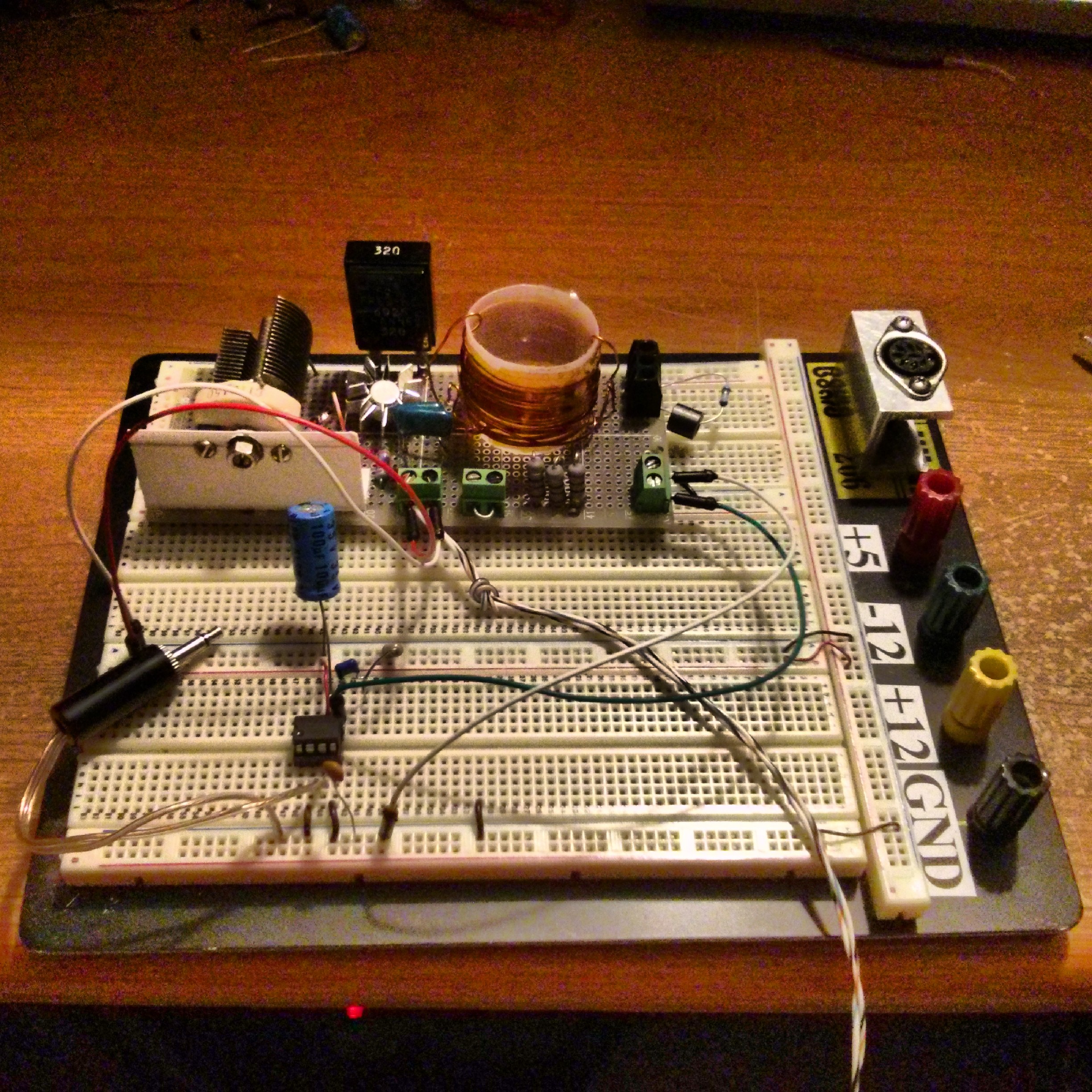
This transmitter also completed with "long wire" antenna put in high location with big diameter of wire. One end of long wire connected to antenna sign at schema. Although this transmitter not completed with antenna impedance matcher, but existence of any good antennas would help electromagnetic wave to spread better. When transmitter output impedance, transmission line characteristic impedance, and antenna input impedance are match, voltage & current at load (antenna) would be maximized, thus maximize power at antenna and transmission distance. If impedances are not match, there would be standing wave at transmission line, causes not all power dissipated at antenna, but portion of power dissipated at transmission line (reflected power), thus decreases antenna effectiveness.
Negative polarity of DC supply connected to ground sign.
RFCs I use are fabricated RFCs. One way to make 0.5349µH (tuning coil):
One way to make 0.5349µH coil
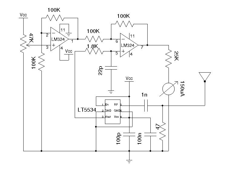
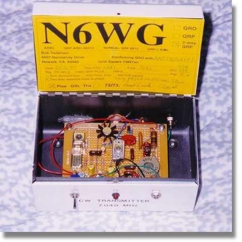
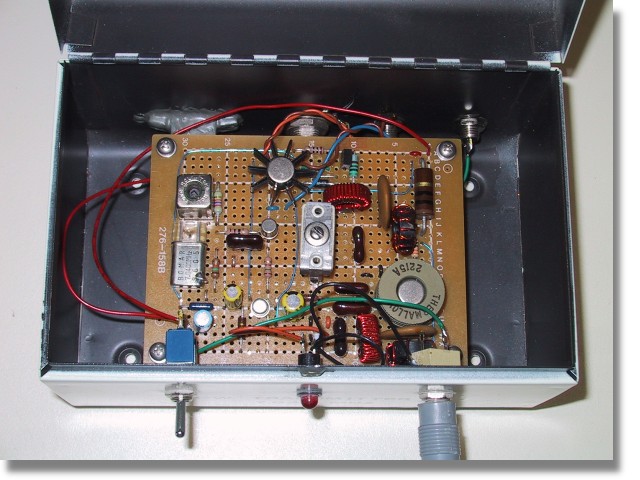
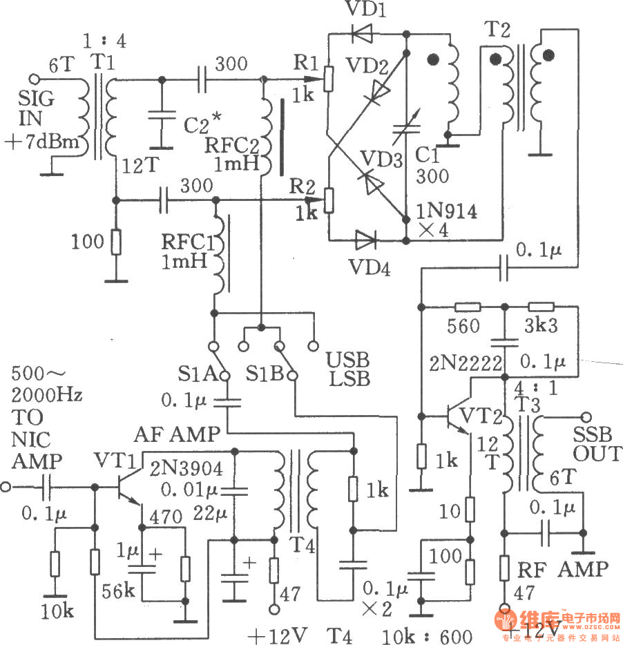
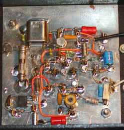
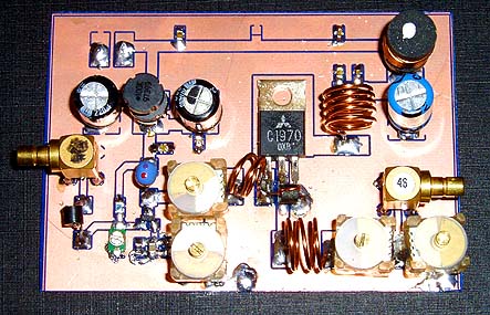
Under are schema of this design and photo of this circuit built at breadboard (if you are not clear with schema, just left click at that schema):

Hobby AM Transmitter


Here is the circuit diagram of a simple AM transmitter circuit that can transmit your audios to your backyard.This circuit is designed with limited  power output to match the FCC regulations and still produces enough amplitude modulation of voice in the medium wave band to satisfy your personal needs.You will love this!.

The circuit has two parts , an audio amplifier and a radio frequency oscillator. The oscillator is built around Q1 (BC109) and related components. The tank circuit with inductance L1 and capacitance VC1 is tunable in the range of 500kHz to 1600KHz. These components can be easily obtained from your old medium wave radio. Q1 is provided with regenerative feedback by connecting the base and collector of Q1 to opposite ends of the tank circuit. C2 ,the 1nF capacitance , couples signals from the base to the top of L1, and C4 the 100pF capacitance ensures that the oscillation is transfered from collector, to the emitter, and through the internal base emitter resistance of the transistor Q2 (BC 109) , back to the base again. The resistor R7 has a vital part in this circuit. It ensures that the oscillation will not be shunted to ground trough the very low value internal emitter resistance, re of Q1(BC 109), and also increases the input impedance such that the modulation signal will not be shunted to ground. Q2 is wired as a common emitter RF amplifier, C5 decouples the emitter resistance and unleashes full gain of this stage. The microphone can be electret condenser microphone and the amount of AM modulation can be adjusted by the 4.7 K variable resistanceR5.

Am Transmitter Circuit Diagram with Parts List.

Am Transmitter Circuit

Am Transmitter Circuit Diagram

Notes .
  • The transmission frequency can be adjusted using the variable capacitance C3.
  • Use a 200uH inductor for the L1 in the tank circuit.
  • Power the circuit using a 9V battery for noise free operation.
  • Use a 30 cm long insulated Copper wire as the antenna.

AM Micropower Transmitter


The picture to the left is a high quality radio transmitter for the A.M. broadcast band. The transmitter legally operates with "micro-power" and will not set any distance records but, unlike simpler designs, the frequency stays put and the fidelity is excellent. Although the schematic looks somewhat complex, the circuitry is easy to build and adjust for experimenters with a little "tweaking" experience. A simple output meter confirms proper signal level and checks antenna tuning while "on the air". Add an audio mixer, tape recorder, and perhaps a CD player and have a near-professional micro-power station.

schematic

Most values are not critical but a few choices must be made carefully for best results. The output tank is tuned to the crystal frequency by selecting the values from the chart above. For example, for a 1 MHz transmitter, the chart indicates 500 pf and 35 uh.  A 33uH and 550pF (470 + 82, perhaps) would be a good start. This chart assumes that a 220 pf capacitor is already connected between the collector and base of the output transistor as indicated in the schematic so the indicated capacitance is in addition to the 220 pf. A variable inductor or capacitor will allow the tank to be fine-tuned for the maximum meter reading with no antenna connected (a few volts with a 10 megohm voltmeter or about 50 microamps with a current meter). After the antenna is connected, the loading inductor in series with the antenna is selected for the minimum meter reading (best antenna loading). (A 3 foot antenna will need about 820 uH for a 1.6 MHz output frequency.) Longer antennas or higher frequencies need less inductance and shorter antennas or lower frequencies will need more. The meter reading should drop by more than half with a reasonably good antenna but the reading can be ignored if sufficient transmit range is achieved. The antenna, which is short relative to the wavelength, is hard to match well because it has a very low radiation resistance in series with a very small capacitor. (The power dissipated in the radiation resistance is the power that is transmitted.) The loading coil helps to resonate out some of the series capacity resulting in more antenna current and thus more radiated power. Some retuning of the tank may be desirable when the loading coil value is changed. A remote radio playing back through a baby monitor or walkie-talkie makes a good signal quality monitor for antenna tuning and positioning.

Note: The antenna in the picture above is just a short metal rod from an old fireplace screen stuck through an important-looking insulator strictly for appearance. It's really too short for optimum range. The 470 ohm resistor across the tank controls the Q when the antenna is short. You might be able to increase or even eliminate that resistor if your antenna and ground system are good enough. Try increasing the value, listening for distortion in a nearby radio.

The crystal can be practically any surplus crystal with a fundamental frequency between 530 kHz and 1.7 MHz in 10 kHz increments but the higher frequencies work best. Choose a crystal frequency away from strong local stations at or above 800 kHz for best transmit range. Proper operation of the oscillator may be verified by probing the junction of the two 1000 pf capacitors with a high impedance oscilloscope probe connected to a scope or frequency counter. Full modulation is achieved by applying about 2 volts peak-to-peak to the base of the current source transistor in the differential amplifier. The modulation voltage varies the current in the diff. amp. away from the nominal 20 ma. setpoint and this modulated current is converted to a clean, high voltage sinewave by the output tuning circuit. The modulated signal may be observed with an oscilloscope connected to the antenna terminal if desired.

The photo above shows a prototype built with metal transistors (just for looks!) and with a few additions like the variable capacitor in series with the crystal for fine tuning and the variable inductor in the collector of the output transistor. Circuit construction is mostly non-critical but a few points should be observed. Ground-plane is not mandatory but it helps control parasitic feedback elements when less than perfect layout techniques are used. The two capacitors across the base-collector leads of the diff-amp transistors should have short leads. Bypass the 15 volt supply well, perhaps with additional 1 uF capacitors not shown in the schematic. The 100 ohm emitter resistor in the modulator may be bypassed with a 22 ohm resistor in series with a 470 uf capacitor to increase the modulation sensitivity to about 1 volt peak-to-peak which is typical of many sources. Eliminating the 22 ohm resistor will increase sensitivity to under 100 mv but the linearity will suffer somewhat.

An amplifying audio mixer may be added as shown in fig. 2 if more than one audio source is to be used. The gain resistor might be near 2.8k for typical 300 mv sources or considerably higher for lower level sources. If the signal level is different for each source then vary the 600 ohm resistors to compensate. A larger resistor will reduce the gain. Set the main gain resistor for the weakest source then increase the 600 ohm resistors in the other channels for the proper balance. A fancy mixer panel could be constructed with potentiometers in place of the resistors. Remember that some op-amps are not sufficiently fast to amplify high fidelity audio. For simplicity, choose an internally-compensated audio op-amp such as the LM833. Since the LM833 is a dual op-amp the second amp could be used as a separate pre-amp for a microphone or other low-level sources using the same schematic as the mixer. The output of this amp simply feeds one of the mixer source inputs.

Applications:

bullet

A continuous-loop tape could give sales information to passing cars. Place a sign that says, "tune to xxxAM for information," next to the house or car that is for sale.

bullet

Transmit special seasonal music at Christmas or Halloween to enhance your decorations. (Use a similar sign.)

bullet

Transmit a cassette player or other audio source to the car radio for better sound.

bullet

Make a pair of toy AM band two-way radios by adding inexpensive AM radios. Or talk between cars on a trip using the car radio for reception.

bullet

Make a baby monitor that works with any AM receiver.

bullet

Transmit control tones to a number of cheap AM receivers for unusual remote control applications.

bullet

Build a fully functional radio station for the kids - complete with vu meters, slide faders, and an "on the air" light.

Besides making a nice general purpose radio transmitter the Personal Radio Station is suitable for some nice practical jokes:

Hide the transmitter with a cassette tape player in your personal effects as you ride in the back seat of a friend's car. (Leave out the meter circuit to keep the size down.) Ask your friend to tune in that new radio station - since your transmitter is crystal controlled it will be at the right place on the dial. What your victim hears is up to you. The circuit will work reasonably well with a single 9 volt battery instead of 15 volts. How about a less than desirable school lunch menu for the kids. Or, if you are younger, an unexpected school closing for the day. (I didn't really suggest that one, did I?) A news announcement of your marriage proposal will get results. Local news personalities will probably be delighted to help make a tape.

Thursday 19 June 2014

1.3W VHF RF Amplifier 2SC1970 88-108 MHz


    1.3W VHF RF Amplifier 2SC1970 88-108 MHz

    1.3W VHF RF Amplifier 2SC1970 88-108 MHz


    This RF power amplifier is based on the transistor 2SC1970 and 2N4427. The output power is about 1.3W and the input driving power is 30-50mW. It will still get your RF signal quit far and I advice you to use a good 50 ohm resistor as dummy load. To tune this amplifier you can either use a power meter/wattmeter, SWR unit or you can do using a RF field meter.

    1.3W VHF RF Amplifier 2SC1970 88-108 MHz

    RF Amplifier Assembly


    Good grounding is very important in a RF system. I use bottom layer as Ground and I connect it with the top with wires to get a good grounding. Make sure you have some cooling at the transistor. In my case I put the 2SC1970 close to the PCB to handle the heat. With good tuning the transistor shouldn't become hot.


    RF Amplifier Printed Circuit Board


    You can download a pdf file which is the black PCB. The PCB is mirrored because the printed side side should be faced down the board during UV exposure. To the right you will find a pic showing the assembly of all components on the same board.This is how the real board should look when you are going to solder the components. It is a board made for surface mounted components, so the copper is on the top layer. I am sure you can still use hole mounted components as well.
    Grey area is copper and each component is draw in different colors all to make it easy to identify for you. The scale of the pdf is 1:1 and the picture at right is magnified with 4 times. Click on the pic to enlarge it.


    Low-Pass Filter


    Some of you might want to add a low-pass filter at the output. I have not added any extra low pass filter in my construction because I don't think it is needed. You can easy find several homepages about low pass filter and how to build them.

    1.3W VHF RF Amplifier 2SC1970 88-108 MHz


Transmitter Circuits Collection


The NOGAnaut QRP Transmitter


The crystal oscillator is the simplest form of transmitter. Normally, oscillators are used to drive buffer amplifiers and power amplifiers, which provide increased output, as well as prevent the output circuit from adversely loading the oscillator.

Most transistors exhibit a characteristic impedance different from the 50-ohm impedance of a well-tuned antenna system. An improper match between the impedance of the transistor and the load (e.g. antenna system) can cause severe power degradation, and worse, can seriously affect the signal, including shifting the oscillator frequency in unpredictable ways.

In the NOGAnaut transmitter, the 2N2222A transistor, which exhibits a characteristic impedance of approximately 200 ohms, is matched to a 50-ohm load via the pi-network filter composed of C1, C2 and L2. The values of these components were chosen to provide a close match between the 200-ohm transistor and a 50-ohm antenna (it is therefore critical that a good 50-ohm antenna system be used with this transmitter). It so happens that these values also form the familiar half-wave harmonic filter, thus satisfying FCC spurious emissions requirements.

NOGAnaut Schematic

Figure 1. NOGAnaut 80M Transmitter Schematic.

Capacitor C5 provides the necessary feedback to begin oscillation. You may find that you can operate your NOGAnaut without this capacitor--stray capacitance in the circuit provides a certain amout of feedback without C5. However, it was found during development of this circuit that the oscillator can have troubles starting at times, therefore it is recommended that you leave C5 in the circuit.

The 0.01 uF capactor, C3, serves as a DC-blocking capactor. At 3.6864 MHz, this capacitor is essentially a dead-short to RF, but blocks the DC current from flowing into the load.

This is a familiar Colpitts oscillator, operated in "common-base mode." The usual base-bypass capacitor is replaced by the capacitance of the crystal. With a 15V supply, this transmitter has been measured to deliver as much as 134 milliwatts into a perfectly matched 50-ohm load ("your mileage may vary"). With a 9V supply, about 20-50 milliwatts should be expected.

The transmitter is keyed by interrupting the positive supply voltage. You can modify this to be grounded keying, if necessary (just interrupt the negative supply voltage instead of the positive voltage). This may be necessary if you use a keyer that expects grounded or negative keying.

For a very good description of crystal oscillators, check out Solid State Design for the Radio Amateur by Wes Hayward, W7ZOI, and Doug DeMaw, W1FB. This is one of the most popular amateur radio books ever written and is packed full of practical information about how solid state circuits behave. It is published by the ARRL, and can be purchased directly from them, as well as from many electronics retailers.

Further information about pi-network filters can be found in The ARRL Electronics Data Book, by Doug DeMaw, W1FB, also published by the ARRL. This book contains most of the nuts and bolts of basic circuit design, and is a must for any ham shack.

http://www.nogaqrp.org/projects/noganaut/circuitdescription.html