Friday 11 July 2014

AM Tone Transmitter


Schematic of circuit

This circuit uses a 4049 hex inverter to form an AM radio tone transmitter. The RF oscillator in this circuit uses one inverter; its frequency is controlled by a 1 MHz microprocessor crystal. Two more inverters amplify its output. Meanwhile, the two inverters at the top left produce an audio tone, which is modulated onto the RF signal by the last inverter. You can tune this in as an audible whine at 1000 kHz on your AM dial. A few inches of wire attached to the output terminal should suffice as a transmitting antenna. This circuit also has another use. It emits harmonics at all whole-number multiples of 1 MHz (i.e. 2 MHz, 3MHz, etc., up to at least 10 MHz) and you can use it to check the dial calibration of a short-wave radio.

Thursday 10 July 2014

Build a RF Dummy Load


A RF dummy load is quite useful when working on transmitters. It allows you to test and adjust the transmitter without an antenna, eliminating interference to other radios on your test frequency. It also presents your transmitter with a proper 50 Ω load so as to not cause any damage to its final RF amplifier stage.

A recent project required me to modify and align twelve UHF transmitters. The transmitters had a 25 watt output and the alignment session on each would be short. Rather than buy a dummy load for this project, I decided to build my own.

The central part of the dummy load is a resistor (or resistors) with a total resistance of 50 Ω and a wattage equal to or greater than your transmitter. The resistors also must be non-inductive which eliminates all the common wire-wound power resistors. Acceptable types of resistors include carbon composition and thick film.

For the resistor in this dummy load I chose a #32-1007 50 Ω flanged termination unit from Florida RF Labs with a rating of 40 watts. Other parts include an aluminum case, heatsink and SO-239 connector.

Dummy load parts

Construction is rather simple. First the heatsink and SO-239 connector are bolted to the case. Be sure to use heatsink compound between the heatsink and case.

Dummy load case

Next holes are drilled and tapped for the flanged termination unit. The flanged termination unit also gets a thin coat of heatsink compound before installation. Its lead is extended with a short piece of wire to reach the SO-239 connector.

Flanged Termination Unit

A quick check with a SWR Meter shows a VSWR of 1.1, an excellent reading.

Sunday 6 July 2014

1 Watt QRP Power Transmitter


1 Watt QRP Power Transmitter
The 1 watt 20 meter QRP transmitter with VXO. This is a nice QRP transmitter that can be used in combination of one of the simple receivers. Normally these designs have only two transistors: one is the X-tal oscillator and the second the final amplifier. A good example is my first QRP rig that is also described somewhere on this site. Here the VXO (Variabele X-tal Oscillator) has a tuning range of 16 kHz. This VXO is buffered with an extra driver stage for a better frequency stability and a varicap diode is used instead of a variabele capacitor. An extra transistor is added for keying the transmitter with a low keying current. What you can do with such a simple 1 watt QRP power transmitter. This is a real low power transmitter, so do not expect that you can do everything with it but... When conditions are normal, you can easily make many QSO's during one afternoon with stations with distances upto 2000 km with a simple inverted V wire dipole antenna! From Europe, I did even make QSO's across the Ocean!

SMALL SINGLE TURN MAGNETIC LOOP


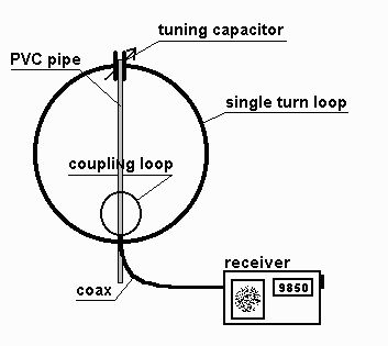
The small single turn magnetic loop (SSTML) antenna consists of a single winding inductor, about 3 feet (1 meter) in diameter, and a tuning capacitor. A second loop, which is one fifth of the diameter of the large loop, is connected to the feedline and this small loop is positioned in the large loop on the opposite side of the tuning capacitor.

Magnetic Loop Antenna

The SSTML has some very interesting properties:

a) It has a small footprint. The loop I describe here looks like a circle in the vertical plane and is just a little over 3 feet (1 meter) in diameter.

b)It is a rather quiet antenna. It doesn’t pick up as much man-made noise from nearby sources as a wire antenna would in the same situation.

c) This antenna is somewhat directional, which can benefit you in two ways. You can either aim (rotate) the antenna for maximum signal strength, or for minimum noise pickup. I prefer to do the latter, and here’s why. This antenna has what is called a deep null on each side of the antenna, the broad sides, meaning that signals coming from that direction will be attenuated quite a bit (30 dB is an often-quoted figure). However, this is mostly true for signals we receive directly, like noise sources, and not so much for signals from broadcast stations coming to us through skywave propagation. I aim the antenna for minimum noise pickup, which results in the best signal to noise ratio. In some situations it is quite possible to fully tune out a noise source such as a TV or computer monitor.

d) Since this antenna is really a tuned circuit, it also acts as a preselector. It only receives well in a narrow bandwidth of a few hundred kilohertz (kHz). The antenna requires retuning if you change the frequency on the radio by a hundred to two hundred kHz. This may sound like a disadvantage, but if you have ever tried a long wire antenna on a rather sensitive receiver, you probably have noticed that your receiver may get overloaded, resulting in hearing multiple stations at once or hearing broadcast stations on frequencies where there really aren’t any. This may make it impossible for you to pull in that DX station you’re really interested in or even make listening to a strong broadcast station rather unpleasant. This antenna will help prevent overloading your receiver.

Wednesday 2 July 2014

27MHz TRANSMITTER with Crystal


Fig 1 shows a simple 27MHz transmitter producing a carrier.


(receiver for this circuit HERE)


The 27MHz transmitter PC board

Here is the circuit made by Lucian Papadopol  iz6nnh@gmail.com
He has created capacitor values by paralleling two values.

This means it produces an unmodulated 27MHz signal and when picked up by a receiver, such as shown in fig 2, the result is a clean, noise-free reception. To increase the output of the transmitter, the 390R resistor is replaced by a 220R. This increases the current from 7mA to 12mA. The resistor could be decreased to 150R for more output.