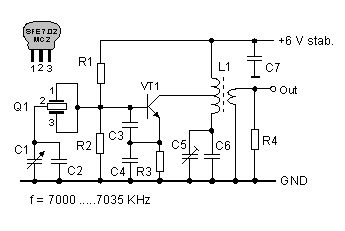
A 7 MHz oscillator with a variable crystal oscillator (VXO) operates very stably, but it allows only a small frequency variation (approx. 5 kHz). In contrast, a VFO with an LC resonant circuit can be tuned over a range of several hundred kHz, but its frequency stability will depend upon its construction. The use of a ceramic resonator as frequency-determining component fulfills both requirements. The following oscillator circuit, which uses a ceramic resonator, offers a tuning range of 35 kHz with good frequency stability. The somewhat unusual resonant LC circuit at the collector of VT1 has two functions. It improves the shape of the output signal and at the same time compensates the amplitude drop starting at approximately 7020 kHz. The transfer characteristic of the ceramic resonator gives this effect. The resonant LC circuit must be adjusted for maximum output amplitude (2Vss) at 7035 kHz. The oscillator needs a regulated voltage of +6 V for proper operation.
The resonant LC circuit can also be tuned to the second, third or forth harmonic. For an improved signal shape however, an extra tuned amplifier stage is necessary. With this adjustment the oscillator is capable for use on 20 meters (14000-14070 KHz), 15 meters (21000-21105 KHz) or 10 meters (28000-28140 KHz).

I have these ceramic resonators SFE7.02.
ReplyDeleteI can pull them from almost 7.0 to over 7.04.
email me if you need/want them
weak_signals @ i-zoom.net
ve3gyy
I gave everyone the wrong address
Deleteshould be
weak_signals @ yahoo.ca
The harmonics are in good places for 20, 15, and 10 meters too
Deleteweak_signals @ yahoo.ca