An easy-to-build and affordable CW rig that puts out about 500 milliwatts on15 meters, this simple modification of W7ZOI's classic two-stage "Universal QRP Transmitter" (also known as the "Little Joe" ) features a VXO circuit that "warps" each crystal frequency by as much as 10kHz or more for increased flexibility. This transmitter's oscillator runs throughout the transmit period; voltage is keyed to the amplifier section while the oscillator is on. After construction,tuneup is a snap: connect a 12-15 VDC power source and 50-ohm dummyl oad or RF wattmeter and tune a monitoring receiver to the anticipated transmit frequency. Flip on the oscillator switch and adjust C3 until a tone is heard on the receiver. Play with C1and notice the shifting of frequency (the crystal frequency DECREASES asC1's capacitance INCREASES). Depress the key and adjust C3 for maximum output. Tuneup adjustment is now complete. Hook up an appropriate antenna (a 40-meter dipoleworks great on 15 meters without use of a transmatch or antenna tuner)and there you go - bring on the sunspots!

Unless otherwise noted, decimal capacitance values are in microfarads(uF);
whole-number values are in picofarads (pF or uuF).
s.m.=silver mica.
* = see below.
C1 - 50pF air-variable capacitor mounted on front panel.
C2 - 10pF trimmer capacitor. OK to use 2pF-8pF fixed capacitor instead. Limits the VXO range and prevents the crystal from "running onits own."
C3 - 60pF mica trimmer capacitor.
L1 - 17 turns #24 enamelled wire on Amidon T50-6 core.
L2 - 3 turns #24 enamelled wire wound over L1 in same direction.
L3 - 9 turns #22 enamelled wire on Amidon T50-6 core.
Q2 - NTE311, 2N3866, 2N3553, RCA4013, or similar NPN RF power transistor. Use heat sink.
Y1, Y2, Y3.... - Fundamental-mode crystals for desired frequencies.
15uH choke - I used a miniature RF choke, but W7ZOI recommends30 turns #28 enamelled wire wound on an Amidon FT37-63 core.
Misc. - Chassis box, rotary switch for the crystals OR a crystal socket for manual crystal switching, SPST switch for the oscillator, knobs(vernier dial for C1 recommended), hookup wire, RG174 miniature coax, solder,mounting hardware, etc.
Construction: I used my usual experimenter's circuit board available from many sources including Radio Shack. Keep all leads short as possible and use RG174 miniature coax for runs that carry RF. Mount the circuit board with the oscillator section & crystals close to C1. Use as manycrystals as you wish to spend the money for - I use three: 21135, 21150,and 21165 kHz which with the VXO covers the middle of the 15-meter Novice subband.
If your station setup doesn't have a filtered keyed-out +V capability from a station controller or other device, the transmitter will also needthe simple KEYING SWITCH depicted below.
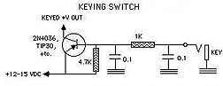
To include the keying switch, connect the keying switch's +12-15 VDC tothe "+12-15 VDC" terminal of the transmitter's oscillator switch and thekeying switch's KEYED +V OUT to the transmitter's "KEYED-IN +12-15 VDC."A plug from the key is then connected to a jack mounted on the front panel.
No comments:
Post a Comment