The circuit of AM transmitter is designed to transmit (amplitude modulated) DSB (double side band) signals. A modulated AM signal consists of a carrier and two symetrically spaced side bands. The two side bands have the same amplitude and carry the same information. In fact, the carrier itself coveys or carries no information. In a 100% modulated AM signal 2/3 rd of the power is wasted in the carrier and only 1/6th of the power is contained in each side band.
In this transmitter we remove the carrier and transmitt only the two side bands. The effective output of the circuit is three times that of an equivalent AM transmitter.
Op Amp IC741 is used here as a microphone amplifier to amplify the voice picked up by the condenser microphone. The output of the op amp is fed to the double balanced modulator (DBM) build around four IN4148 diodes. The modulation level can be adjusted with the help of preset VR1.
The carrier is generated using crystal oscillator wired around BC548 transistor T2. The carrier is further amplified by transistor T1, which also acts as a buffer between carrier oscillator and the balanced modulator. The working frequency of the transmitter can be changed by using crystals of different frequencies. For multi frequency operation, selection of different crystals can be made using a selector switch.
Ths output of the DBM contains only the product (of audio and carrier) frequencies. The DBM suppresses both the input signals and produces double side band suppressed carrier (DSBSC) at its output. However, since the diodes used in the balanced modulator are not fully matched, the output of the DBM does contain some residual carrier. This is known as carrier leakage. By adjusting the 100 ohm preset VR2 and trimmer C7 you can null the carrier leakage. To receive DSB signals you need a beat frequency oscillator to reinsert the missing carrier. If you don't have a beat frequency oscillator, or want to transmitt only AM signal, adjust preset VR2 to leak some carrier so that you can receive the signals on any ordinary radio receiver. In AM mode 100% modulation can be attained by adjusting preset VR1 and VR2.
The DSBSC signal available at the output of the balanced modulator is amplified by two stages of RF linear amplifiers. Transistor 2N2222A (T3) is used as an RF pre amplifier, which provides enough signal amplification to drive the final power amplifier build around transistor SL100B. The output of the final power amplifier is connected to the antenna.
All coils are to be wound ferrite balun core (same as used in TV balun transformer of size 1.4 cm * 0.6 cm) using 24 swg enameled copper wire. Proper heat sink should be provided for SL100B transistor used as final power amplifier.
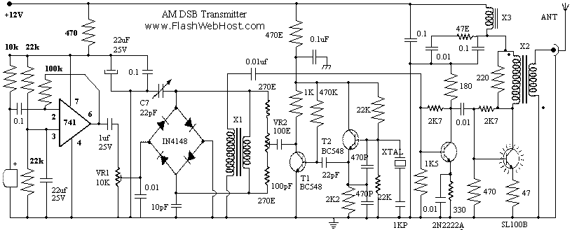
X1 - 8+8 Turns Bifalar 24 SWG On TV Balune Core
X2 - Primary 12 Turns, Secondary 4 Turns. 24 SWG on TV Balun Core (dot indicates start of coil).
X3 - 20 Turns 24 SWG on TV Balun Core
Range of the circuit depends on the type of antenna used. It is very important to use matched antenna to radiate the signals effectively. I used horizontal dipole antenna, which is simple and easy to construct. For 7 MHz, ie 40 meter ham band the length of dipole antenna will be 20 meter. Use 75 Ohms co-axial cable to connect antenna and transmitter. I was able to get 57 report from station 80 kilometer away. You can easily add a Linear RF amplifier using IRF830 to get more power.
Circuit designed by YUJIN BOBY VU3PRX
No comments:
Post a Comment